Infiniti M45 (Y34). Manual - part 767


  Index      Infiniti     Infiniti M45 (Y34) - service repair manual 2004 year


Search            copyright infringement  


Content   ..  765  766  767  768   ..


Infiniti M45 (Y34). Manual - part 767


AUTOMATIC DRIVE POSITIONER

SE-89

C

D

E

F

G

H

J

K

L

M

A

B

SE

5. 

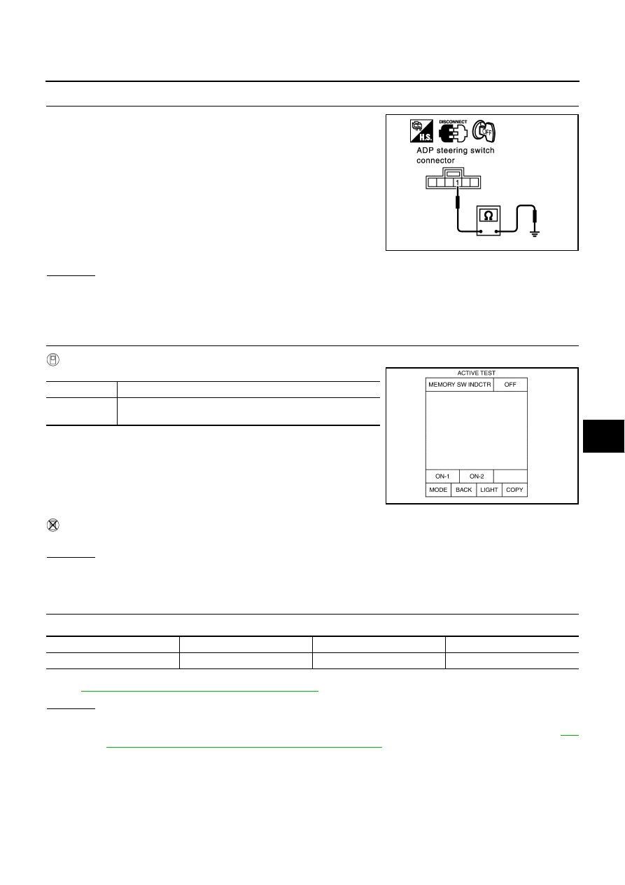
CHECK ADP STEERING SWITCH GROUND CIRCUIT

Check continuity between ADP steering switch connector M51 termi-
nal 1 (B) and body ground.

OK or NG

OK

>> Check the harness and connector.

NG

>> Repair or replace harness between ADP steering switch and body ground. 

Seat Memory Indicator Lamp System Inspection

AIS001KJ

1. 

CHECK FUNCTION

With CONSULT-II

With “MEMORY SW INDCTR” in ACTIVE TEST, Check operation.

Without CONSULT-II

GO TO 2.
OK or NG

OK

>> System is OK.

NG

>> GO TO 2.

2. 

CHECK FUSE

Check if any of the following fuses for fuse block (J/B) are blown.

NOTE:
Refer to 

SE-17, "Component Parts and Harness Connector Location"

 .

OK or NG

OK

>> GO TO 2.

NG

>> If fuse is blown, be sure to eliminate cause of malfunction before installing new fuse, refer to 

SE-

17, "Component Parts and Harness Connector Location"

 .

1 (B) – Ground

: Continuity should exist.

PIIA3310E

Test item

Description

MEMORY SW 
INDCTR

The memory switch indicator is lit by receiving the drive signal.

PIIA0319E

COMPONENT PARTS

TERMINAL NO. (SIGNAL)

AMPERE

FUSE NO.

Fuse block (J/B) No.1

9C (BAT power supply)

10A

#8

SE-90

AUTOMATIC DRIVE POSITIONER

3. 

CHECK SEAT MEMORY SWITCH POWER SUPPLY CIRCUIT

1.

Turn ignition switch OFF.

2.

 Disconnect seat memory switch connector.

3.

Check voltage between seat memory switch connector D3 ter-
minal 5 (L) and body ground.

OK or NG

OK

>> GO TO 4.

NG

>> Check following.

10A fuse [No. 8, located in the fuse block (J/B) No. 1]

Harness for open short between seat memory switch and fuse.

4. 

CHECK HARNESS CONTINUITY

1.

Disconnect BCM connector.

2.

Check continuity between BCM connector M4 terminals 106 (Y/
G), 112 (L/W) and seat memory switch connector D3 terminals 6
(Y/G), 7 (L/W). 

3.

Check continuity between BCM connector M4 terminals 106 (Y/
G), 112 (L/W) and body ground.

OK or NG

OK

>> GO TO 5.

NG

>> Repair or replace harness between BCM and memory switch.

5. 

CHECK SEAT MEMORY SWITCH INDICATOR SIGNAL

Check voltage between BCM connector M4 terminals 106 (Y/G), 112
(L/W) and body ground.

OK or NG

OK

>> Replace BCM.

NG

>> Replace seat memory switch.

5 (L) – Ground

: Battery voltage

PIIA3311E

106 (Y/G) – 6 (Y/G)

: Continuity should exist.

112 (L/W) – 7 (L/W)

: Continuity should exist.

106 (Y/G) – Ground

: Continuity should not exist.

112 (L/W) – Ground

: Continuity should not exist.

PIIA3312E

106 (Y/G) – Ground

: Battery voltage

112 (L/W) – Ground

: Battery voltage

PIIA3313E

AUTOMATIC DRIVE POSITIONER

SE-91

C

D

E

F

G

H

J

K

L

M

A

B

SE

Lumber Support Motor Circuit Inspection

AIS002CL

1. 

CHECK LUMBER SUPPORT SWITCH

1.

Turn ignition switch OFF.

2.

Disconnect front power seat switch (driver side) connector.

3.

Check voltage between power seat switch (driver side) connec-
tor B144 terminal 16 (R) and body ground.

OK or NG

OK

>> GO TO 2.

NG

>> Repair or replace harness between fuse block (J/B) and power seat switch (Driver side). 

2. 

CHECK LUMBER SUPPORT SWITCH

Check continuity power seat switch.

OK or NG

OK

>> GO TO 3.

NG

>> Replace power seat switch.

3. 

CHECK LUMBER SUPPORT MOTOR HARNESS

1.

Disconnect lumber support motor connector.

2.

Check continuity between power seat switch connector (driver
side) B144 terminal 3 (GY), 5 (W/B) and lumber support motor
connector B195 terminal 3 (GY), 5 (W/B).

3.

Check continuity between power seat switch connector (driver
side) B144 terminal 3 (GY), 5 (W/B) and body ground.

OK or NG

OK

>> GO TO 4.

NG

>> Repair or replace harness between power seat switch (driver side) and lumber support motor.

16 (R) – Ground

: Battery voltage

PIIA3376E

Con-

nector

Terminal

Condition

Continuity

(+)

(–)

B144

16 

Lumber support switch forward.

 Continuity should 

exist

15

Lumber support switch backward.

Continuity should 

exist

16 

Lumber support switch backward.

Continuity should 

exist

15 

Lumber support switch forward.

Continuity should 

exist

PIIA3377E

3 (GY) 

 3 (GY)

: Continuity should exist.

5 (W/B) 

 5 (W/B)

: Continuity should exist.

3 (GY) 

 Ground

: Continuity should not exist.

5 (W/B) 

 Ground

: Continuity should not exist.

PIIA3379E

SE-92

AUTOMATIC DRIVE POSITIONER

4. 

 LUMBER SUPPORT SWITCH INSPECTION

Check continuity between power seat switch connector (driver side)
B144 terminal 15 (B) and body ground.

OK or NG

OK

>> Replace rumbler support motor.

NG

>> Repair or replace harness between power seat switch (driver side) and body ground. 

15 (B) – Ground

: Continuity should exist.

PIIA3375E


Content   ..  765  766  767  768   ..