Infiniti M45 (Y34). Manual - part 641


  Index      Infiniti     Infiniti M45 (Y34) - service repair manual 2004 year


Search            copyright infringement  


Content   ..  639  640  641  642   ..


Infiniti M45 (Y34). Manual - part 641


HEADLAMP (FOR CANADA) - DAYTIME LIGHT SYSTEM -

LT-71

C

D

E

F

G

H

I

J

L

M

A

B

LT

4. 

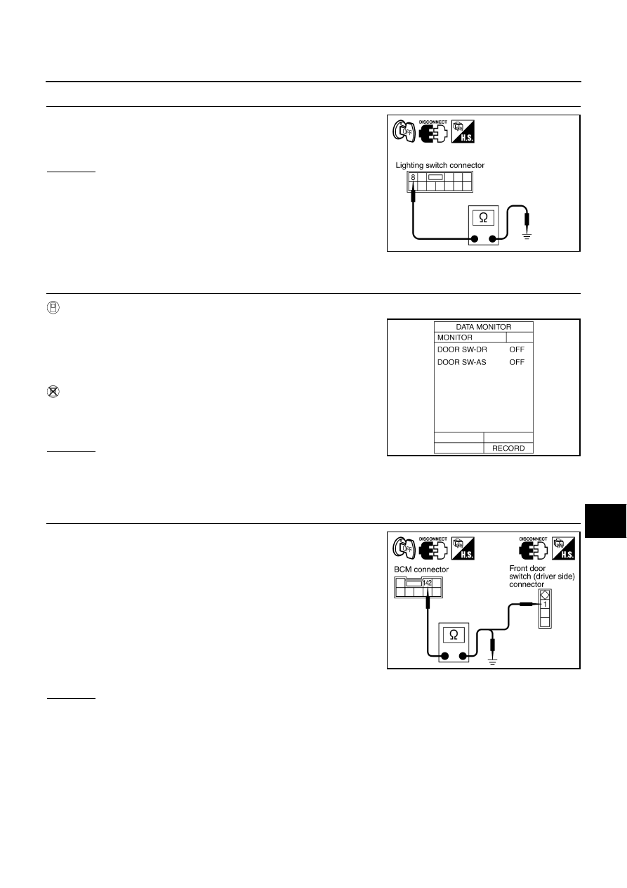
CHECK LIGHTING SWITCH GROUND CIRCUIT

Check continuity between lighting switch harness connector M55 ter-
minal 8 (B) and ground.

OK or NG

OK

>> INSPECTION END

NG

>> Repair harness ground circuit.

Front Door Switch Circuit Inspection

AKS003SK

1. 

CHECK DOOR SWITCH SIGNAL

With CONSULT-II

1.

Select “INTERIOR ILLUMINATION” of “IVMS” on “SELECT
SYSTEM” screen. 

2.

Operate each door via “DOOR SW-DR” and “DOOR SW-AS” on
“DATA MONITOR” screen and make sure that the switch turns
on and off as commanded.

Without CONSULT-II

Open and close the front door (driver side, passenger side) and
make sure that the switch turns on and off by “switch monitor” in
the self-diagnosis function.

OK or NG

OK

>> INSPECTION END

NG

>>

When front door switch (driver side) is malfunction, go to 2.

When front door switch (passenger side) is malfunction, go to 4.

2. 

CHECK FRONT DOOR SWITCH (DRIVER SIDE) CIRCUIT

1.

Turn ignition switch OFF.

2.

Disconnect BCM connector and front door switch (driver side)
connector.

3.

Check continuity between BCM harness connector B4 terminal
142 (R/Y) and front door switch (driver side) harness connector
B20 terminal 1 (R/Y).

4.

Check continuity between BCM harness connector B4 terminal
142 (R/Y) and ground.

OK or NG

OK

>> GO TO 3.

NG

>> Repair harness or connector.

8 (B) - Ground

: Continuity should exist.

PKIA5904E

SKIA3814E

142 (R/Y) - 1 (R/Y)

: Continuity should exist.

142 (R/Y) - Ground

: Continuity should not exist.

PKIA5905E

LT-72

HEADLAMP (FOR CANADA) - DAYTIME LIGHT SYSTEM -

3. 

CHECK FRONT DOOR SWITCH (DRIVER SIDE)

Check front door switch (driver side).

OK or NG

OK

>> Replace BCM.

NG

>> Replace front door switch (driver side).

4. 

CHECK FRONT DOOR SWITCH (PASSENGER SIDE) CIRCUIT

1.

Turn ignition switch OFF.

2.

Disconnect BCM connector and front door switch (passenger
side) connector.

3.

Check continuity between BCM harness connector M4 terminal
37 (LG) and front door switch (passenger side) harness connec-
tor B220 terminal 1 (LG).

4.

Check continuity between BCM harness connector M4 terminal
37 (LG) and ground.

OK or NG

OK

>> GO TO 5.

NG

>> Repair harness or connector.

5. 

CHECK FRONT DOOR SWITCH (PASSENGER SIDE)

Check front door switch (passenger side).

OK or NG

OK

>> Replace BCM.

NG

>> Replace front door switch (passenger side).

Switch released (ON)

: Continuity should exist.

Switch pressed (OFF)

: Continuity should not exist.

37 (LG) - 1 (LG)

: Continuity should exist.

37 (LG) - Ground

: Continuity should not exist.

PKIA5907E

Switch released (ON)

: Continuity should exist.

Switch pressed (OFF)

: Continuity should not exist.

HEADLAMP (FOR CANADA) - DAYTIME LIGHT SYSTEM -

LT-73

C

D

E

F

G

H

I

J

L

M

A

B

LT

Headlamp Battery Saver Control Unit Circuit Inspection

AKS003SL

1. 

CHECK RAP SIGNAL

1.

Turn ignition switch OFF.

2.

Disconnect battery saver control unit connector.

3.

Turn ignition switch ON.

4.

Check voltage between headlamp battery saver control unit har-
ness connector M34 terminal 10 (Y/R) and ground after turning
off ignition switch.

OK or NG

OK

>> INSPECTION END

NG

>> GO TO 2.

2. 

CHECK RAP SIGNAL CIRCUIT

1.

Disconnect BCM connector.

2.

Check continuity between headlamp battery saver control unit
harness connector M34 terminal 10 (Y/R) and BCM harness
connector R4 terminal 135 (Y/G).

3.

Check continuity between headlamp battery saver control unit
harness connector M34 terminal 10 (Y/R) and ground.

OK or NG

OK

>> Replace BCM.

NG

>> Repair harness or connector.

Daytime Light Control Unit Circuit Inspection

AKS003SM

1. 

CHECK PARKING BRAKE SWITCH SIGNAL 

1.

Turn ignition switch OFF.

2.

Disconnect daytime light control unit.

3.

Check continuity between daytime light control unit harness con-
nector E26 terminal 17 (Y/R) and ground.

OK or NG

OK

>> GO TO 3.

NG

>> GO TO 2.

Connector

Terminal 

(Wire color)

Condition

Voltage

M34

10 (Y/R)

Within 45 seconds after ignition 
switch is turned off

Approx. 0V

Front door is opened or more than 
45 seconds after ignition switch is 
turned off

Battery voltage

PKIA5909E

10 (Y/R) - 135 (Y/R)

: Continuity should exist.

10 (Y/R) - Ground

: Continuity should not exist.

PKIA5910E

Terminals

Parking brake 

condition

Continuity

Connector

Terminal (Wire color)

E26

17 (Y/R)

Ground

Applied

Yes

Released

No

PKIA5911E

LT-74

HEADLAMP (FOR CANADA) - DAYTIME LIGHT SYSTEM -

2. 

CHECK PARKING BRAKE SWITCH CIRCUIT

1.

Disconnect parking brake switch connector.

2.

Check continuity between daytime light control unit harness con-
nector E26 terminal 17 (Y/R) and parking brake switch harness
connector M8 terminal 1 (Y/R).

3.

Check continuity between daytime light control unit harness con-
nector E26 terminal 17 (Y/R) and ground.

OK or NG

OK

>> Check parking brake switch and case ground.

NG

>> Repair harness or connector.

3. 

CHECK ALTERNATOR CIRCUIT

1.

Disconnect alternator connector.

2.

Check continuity between daytime light control unit harness con-
nector E27 terminal 1 (W/R) and alternator harness connector
E310 terminal 3 (W/R).

3.

Check continuity between daytime light control unit harness con-
nector E27 terminal 1 (W/R) and ground.

OK or NG

OK

>> INSPECTION END

NG

>> Repair harness or connector.

Aiming Adjustment

AKS002FM

Refer to 

LT-39, "Aiming Adjustment"

  in “HEADLAMP (FOR USA)”.

Bulb Replacement

AKS002FN

Refer to 

LT-41, "Bulb Replacement"

  in “HEADLAMP (FOR USA)”.

Removal and Installation

AKS002FO

Refer to 

LT-42, "Removal and Installation"

  in “HEADLAMP (FOR USA)”.

Disassembly and Assembly

AKS002FP

Refer to 

LT-43, "Disassembly and Assembly"

  in “HEADLAMP (FOR USA)”.

17 (Y/R) - 1 (Y/R)

: Continuity should exist.

17 (Y/R) - Ground

: Continuity should not exist.

PKIA5912E

1 (W/R) - 3 (W/R)

: Continuity should exist.

1 (W/R) - Ground

: Continuity should not exist.

PKIA5913E


Content   ..  639  640  641  642   ..