Infiniti M45 (Y34). Manual - part 632


  Index      Infiniti     Infiniti M45 (Y34) - service repair manual 2004 year


Search            copyright infringement  


Content   ..  630  631  632  633   ..


Infiniti M45 (Y34). Manual - part 632


HEADLAMP (FOR USA)

LT-35

C

D

E

F

G

H

I

J

L

M

A

B

LT

2. 

CHECK HARNESS CIRCUIT
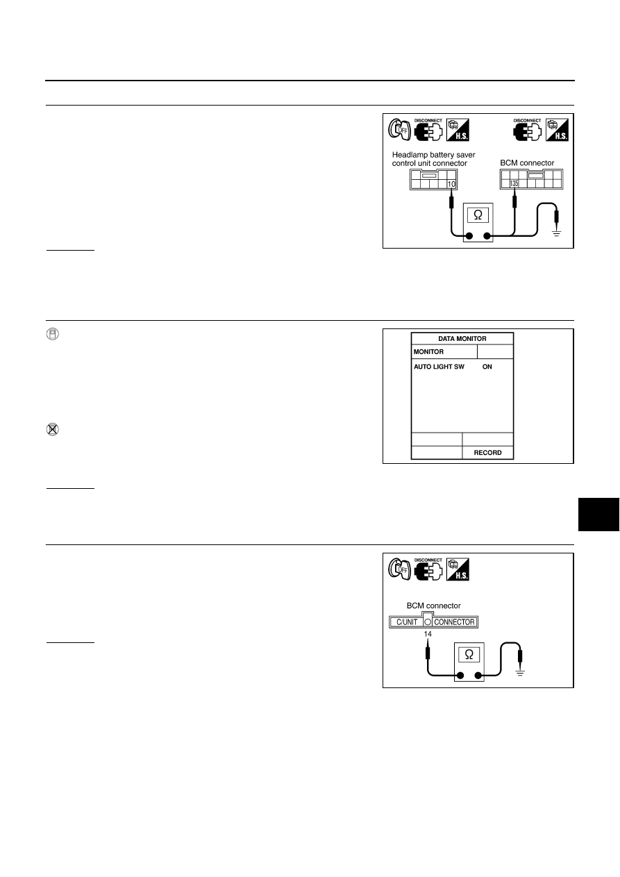
1.

Disconnect BCM connector.

2.

Check continuity between headlamp battery saver control unit
harness connector M34 terminal 10 (Y/R) and BCM harness
connector R4 terminal 135 (Y/G).

3.

Check continuity between headlamp battery saver control unit
harness connector M34 terminal 10 (Y/R) and ground.

OK or NG

OK

>> Replace BCM.

NG

>> Repair harness or connector.

Lighting Switch (AUTO) System Inspection

AKS002F7

1. 

CHECK LIGHTING SWITCH (AUTO) SIGNAL

With CONSULT-II

Operate lighting switch via “AUTO LIGHT SWITCH” on “DATA
MONITOR” screen and make sure that lamp turns on and off as
commanded.

Without CONSULT-II

Operate the lighting switch via “switch monitor” of self-diagnosis
function make sure that the lamp turns on and off as com-
manded.

OK or NG

OK

>> INSPECTION END

NG

>> GO TO 2.

2. 

 CHECK LIGHTING SWITCH (AUTO) SIGNAL CIRCUIT

1.

Turn ignition switch OFF.

2.

Disconnect BCM connector.

3.

Check continuity between BCM harness connector M4 terminal
14 (Y/L) and ground while operating lighting switch in AUTO.

OK or NG

OK

>> INSPECTION END

NG

>> GO TO 3.

10 (Y/R) - 135 (Y/G)

: Continuity should exist.

10 (Y/R) - Ground

: Continuity should not exist.

PKIA5866E

Lighting switch AUTO

: AUTO LIGHT SW ON

Lighting switch OFF

: AUTO LIGHT SW OFF

SKIA0451E

14 (Y/L) - Ground

: Continuity should exist.

PKIA5867E

LT-36

HEADLAMP (FOR USA)

3. 

CHECK LIGHTING SWITCH (AUTO) CIRCUIT

1.

Disconnect lighting switch connector.

2.

Check continuity between BCM harness connector M4 terminal
14 (Y/L) and lighting switch harness connector M55 terminal 42
(Y/L).

3.

Check continuity between BCM harness connector M4 terminal
14 (Y/L) and ground.

OK or NG

OK

>> GO TO 4.

NG

>> Repair harness or connector.

4. 

CHECK LIGHTING SWITCH

Check continuity of the lighting switch. Refer to 

LT-102, "Switch Circuit Inspection"

 .

OK or NG

OK

>> Check harness ground circuit.

NG

>> Replace lighting switch.

Optical Sensor System Inspection

AKS002F8

1. 

CHECK OPTICAL SENSOR OUTPUT SIGNAL

With CONSULT-II

Using “OPTICAL SEN” on “DATA MONITOR” screen, check differ-
ence in the voltage when light is applied to optical sensor and light is
not applied to optical sensor.

Without CONSULT-II

1.

Turn ignition switch ON.

2.

Check voltage between BCM harness connector M4 terminal 52
(G/R) and ground when light is applied to optical sensor and
light is not applied to optical sensor.

OK or NG

OK

>> INSPECTION END

NG

>> GO TO 2.

14 (Y/L) - 42 (Y/L)

: Continuity should exist.

14 (Y/R) - Ground

: Continuity should not exist.

PKIA5868E

Condition

Reference value of data monitor

Light is applied to optical sensor.

More than 3 V

Light is not applied to optical sensor.

Approx. 0.5 V

Terminals

Condition

Voltage

(+)

(-)

Connector

Terminal (Wire color)

M4

52 (G/R)

Ground

Light is applied to 
optical sensor.

More than 3 V

Light is not applied 
to optical sensor.

Approx. 0.5 V

SKIA0454E

PKIA5869E

HEADLAMP (FOR USA)

LT-37

C

D

E

F

G

H

I

J

L

M

A

B

LT

2. 

CHECK OPTICAL SENSOR POWER SUPPLY CIRCUIT

1.

Turn ignition switch OFF.

2.

Disconnect BCM connector and optical sensor connector.

3.

Check continuity between BCM harness connector M4 terminal
59 (SB) and optical sensor harness connector M110 terminal 1
(SB).

4.

Check continuity between BCM harness connector M4 terminal
59 (SB) and ground.

OK or NG

OK

>> GO TO 3.

NG

>> Repair harness or connector.

3. 

CHECK OPTICAL SENSOR SIGNAL CIRCUIT

1.

Check continuity between BCM harness connector M4 terminal
52 (G/R) and optical sensor harness connector M110 terminal 2
(G/R).

2.

Check continuity between BCM harness connector M4 terminal
52 (G/R) and ground.

OK or NG

OK

>> GO TO 4.

NG

>> Repair harness or connector.

4. 

CHECK OPTICAL SENSOR GROUND CIRCUIT

1.

Check continuity between BCM harness connector M4 terminal
58 (Y/B) and optical sensor harness connector M110 terminal 3
(Y/B).

2.

Check continuity between BCM harness connector M4 terminal
58 (Y/B) and ground.

OK or NG

OK

>> GO TO 5.

NG

>> Repair harness or connector.

59 (SB) - 1 (SB)

: Continuity should exist.

59 (SB) - Ground

: Continuity should not exist.

PKIA5870E

52 (G/R) - 2 (G/R)

: Continuity should exist.

52 (G/R) - Ground

: Continuity should not exist.

PKIA5871E

58 (Y/B) - 3 (Y/B)

: Continuity should exist.

58 (Y/B) - Ground

: Continuity should not exist.

PKIA5872E

LT-38

HEADLAMP (FOR USA)

5. 

CHECK OPTICAL SENSOR POWER SUPPLY OUTPUT SIGNAL

1.

Connect BCM connector.

2.

Check voltage between BCM harness connector M4 terminal 59
(SB) and ground.

OK or NG

OK

>> Replace optical sensor.

NG

>> Replace BCM.

Headlamp Relay System Inspection

AKS002F9

1. 

CHECK HEADLAMP RELAY CONTROL SIGNAL 

1.

Turn ignition switch OFF.

2.

Disconnect BCM connector.

3.

Check voltage between BCM harness connector M4 terminal 5
(W/PU) and ground while operating the lighting switch in OFF.

OK or NG

OK

>> INSPECTION END

NG

>> Check harness for open or short between BCM and

headlamp relay-1, headlamp relay- 2.

Tail Lamp Relay System Inspection

AKS002FA

1. 

CHECK TAIL LAMP RELAY CONTROL SIGNAL

1.

Turn ignition switch OFF.

2.

Disconnect BCM connector.

3.

Check voltage between BCM harness connector M4 terminal 11
(LG/B) and ground while operating the lighting switch in OFF.

OK or NG

OK

>> GO TO 2.

NG

>> Check harness for open or short between BCM and tail

lamp relay.

2. 

CHECK TAIL LAMP SIGNAL

Check voltage between BCM harness connector M4 terminal 3 (R/L)
and ground while operating lighting switch in 1ST position.

OK or NG

OK

>> INSPECTION END

NG

>> GO TO 3.

59 (SB) - Ground

: Approx. 5V

PKIA6063E

5 (W/PU) - Ground

: Battery voltage should exist.

PKIA5873E

11 (LG/B) - Ground

: Battery voltage should exist.

PKIA5874E

3 (R/L) - Ground

: Battery voltage should exist.

PKIA5875E


Content   ..  630  631  632  633   ..