Infiniti M45 (Y34). Manual - part 600
REVERSE INTERLOCK DOOR MIRROR SYSTEM
GW-111
C
D
E
F
G
H
J
K
L
M
A
B
GW
OK or NG ?
OK
>> GO TO 4.
NG
>> Repair or replace harness
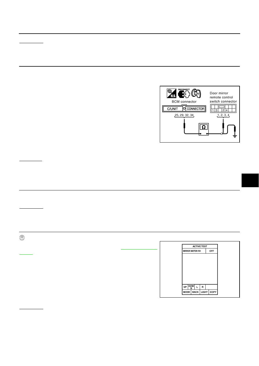
4.
HARNESS CONTINUITY INSPECTION
1.
Disconnect BCM harness connector.
2.
Check continuity between BCM connector M4 terminals 25, 29, 32, 34 and door mirror remote control
switch connector M19 terminals 1, 2, 3, 4.
3.
Check continuity between BCM connector M4 terminals 25, 29,
32, 34 and ground.
OK or NG?
OK
>> Check connector for damage or loose connection.
NG
>> Repair or replace harness between BCM and door mirror remote control switch.
Mirror Motors Circuit Inspection
AIS001XS
1.
DOOR MIRROR FUNCTION INSPECTION
Check the following items.
Operation malfunction caused by a foreign object caught in door mirror face edge.
OK or NG ?
OK
>> GO TO 2.
NG
>> Repair the malfunctioning parts, and check the symptom again.
2.
MIRROR MOTOR INSPECTION
With CONSULT–II
Check the operation with “MIRROR MOTOR RH ” or “MIRROR
MOTOR LH ” in the ACTIVE TEST. Refer to
.
NOTE:
If CONSULT-II is not available, skip this procedure and go to the next
step.
OK or NG ?
OK
>> System is OK.
NG
>> GO TO 3.
25 (G/R) – 2 (G/R)
: Continuity should exist.
29 (LG/R) – 1 (LG/R)
: Continuity should exist.
32 (L/W) – 3 (L/W)
: Continuity should exist.
34 (P/L) – 4 (P/L)
: Continuity should exist.
25 (G/R) – Ground
: Continutiy should not exist.
29 (LG/R) – Ground
: Continuity should not exist.
32 (L/W) – Ground
: Conitnuity should not exist.
34 (P/L) – Ground
: Continuity should not exist.
PIIB0562E
PIIA0202E