Infiniti M45 (Y34). Manual - part 568
 

  Index      Infiniti     Infiniti M45 (Y34) - service repair manual 2004 year


Search            copyright infringement  


Content   ..  566  567  568  569   ..


Infiniti M45 (Y34). Manual - part 568


CONSULT-II CHECKING SYSTEM

GI-37

C

D

E

F

G

H

I

J

K

L

M

B

GI

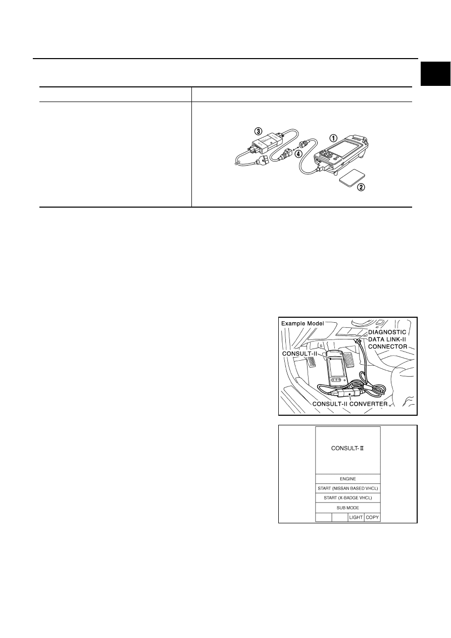
Checking Equipment 

AAS00068

When ordering the following equipment, contact your NISSAN/INFINITI distributor.

NOTE:

●

The CONSULT-II must be used in conjunction with a program card.
CONSULT-II does not require loading (Initialization) procedure.

●

Be sure the CONSULT-II is turned off before installing or removing a program card.

CAUTION:

Previous CONSULT-II “I” and “Y” DLC-I and DLC-II cables should NOT be used anymore because their
DDL connector pins can be damaged during cable swapping.

CONSULT-II Start Procedure

AAS000I3

NOTE:
Turning ignition switch off when performing CAN diagnosis could cause CAN memory to be erased.

1.

Connect CONSULT-II and CONSULT-II CONVERTER to the
data link connector.

2.

If necessary, turn on the ignition switch.

3.

Touch "START(NISSAN BASED VHCL)" or System Shortcut key
(eg: ENGINE) on the screen.

Tool name

Description

NISSAN CONSULT-II

1. CONSULT-II unit (Tester internal soft: Resident 

version 3.3.0) and accessories

2. Program card AED03E and AEN02C (For 

NATS)

3. CONSULT-II CONVERTER

4. “CONSULT-II Pigtail” Cable

SAIA0363E

PAIA0070E

SAIA0450E

GI-38

CONSULT-II CHECKING SYSTEM

CONSULT-II Data Link Connector (DLC) Circuit

AAS0007C

TAWA0002E

CONSULT-II CHECKING SYSTEM

GI-39

C

D

E

F

G

H

I

J

K

L

M

B

GI

INSPECTION PROCEDURE 

If the CONSULT-II cannot diagnose the system properly, check the following items.

NOTE:
The DDL1 and DDL2 circuits from DLC pins 12, 13, 14 and 15 may be connected to more than one system. A
short in a DDL circuit connected to a control unit in one system may affect CONSULT-II access to other sys-
tems.

Symptom

Check item

CONSULT-II cannot access 
any system.

●

CONSULT-II DLC power supply circuit (Terminal 8) and ground circuit (Terminal 4) (For detailed 
circuit, refer to “MIL & Data Link Connectors Wiring Diagram” in EC section.)

●

CONSULT-II DLC cable and CONSULT-II CONVERTER

CONSULT-II cannot access 
individual system. (Other sys-
tems can be accessed.)

●

CONSULT-II program card (Check the appropriate CONSULT-II program card for the system. 
Refer to "Checking Equipment".)

●

Power supply and ground circuit for the control unit of the system (For detailed circuit, refer to wir-
ing diagram for each system.)

●

Open or short circuit between the system and CONSULT-II DLC (For detailed circuit, refer to wiring 
diagram for each system.)

GI-40

LIFTING POINT

LIFTING POINT

PFP:00000

Special Service Tools 

AAS0006A

The actual shapes of Kent-Moore tools may differ from those of special service tools illustrated here.

CAUTION:

●

Every time the vehicle is lifted up,  maintain the complete vehicle curb condition.

●

Since the vehicle's center of gravity changes when removing main parts on the front side (engine,
transmission, suspension etc.), support a jack up point on the rear side garage jack with a mission
jack or  equivalent. 

●

Since the vehicle's center of gravity changes when removing main parts on the rear side (rear axle,
suspension, etc.), support a jack up point on the front side garage jack with a mission jack or
equivalent. 

●

Be careful not to smash or do not do anything that would affect piping parts.

Garage Jack and Safety Stand 

AAS0006B

WARNING:

●

Park the vehicle on a level surface when using the jack. Make sure to avoid damaging pipes,
tubes, etc. under the vehicle.

●

Never get under the vehicle while it is supported only by the jack. Always use safety stands when
you have to get under the vehicle.

Tool number

(Kent-Moore No.)

Tool name

Description

LM4086-0200
(   -   )
Board on attachment

LM4519-0000
(   -   )
Safety stand attachment

S-NT001

S-NT002


Content   ..  566  567  568  569   ..