Infiniti M45 (Y34). Manual - part 556


  Index      Infiniti     Infiniti M45 (Y34) - service repair manual 2004 year


Search            copyright infringement  


Content   ..  554  555  556  557   ..


Infiniti M45 (Y34). Manual - part 556


COIL SPRING AND STRUT

FSU-11

C

D

F

G

H

I

J

K

L

M

A

B

FSU

ASSEMBLY

CAUTION:

Make sure piston rod on strut assembly is not damaged when attaching components to strut assem-
bly.

1.

Install strut attachment (special service tool) to strut assembly and fix it in a vice.

CAUTION:

When installing strut attachment (special service tool) to strut assembly, wrap a shop cloth around
strut assembly to protect it from damage.

2.

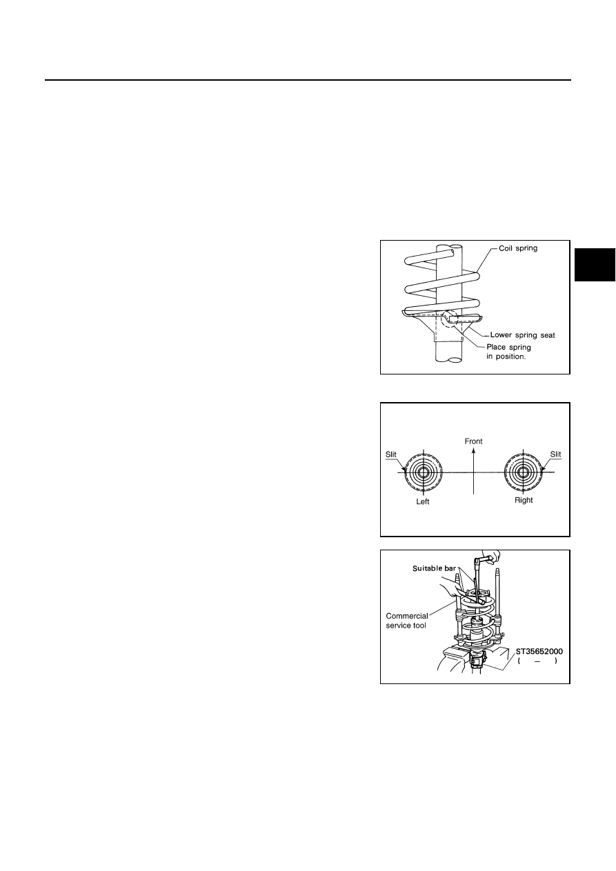
Compress coil spring using a spring compressor (commercial service tool), and install it onto strut assem-
bly.

CAUTION:

Face tube side of coil spring downward. Align lower end
to spring seat as shown in the figure.

Be sure spring compressor (commercial service tool) is
securely attached to coil spring. Compress coil spring.

3.

Apply soapy water to bound bumper and insert into strut mount-
ing insulator.

CAUTION:

Do not use machine oil.

4.

Install rubber seat, spring upper seat, strut mounting insulator.

Installation position of spring upper seat is as shown in the fig-
ure.

5.

Fix strut mounting insulator, then tighten piston rod lock nut with
the specified torque.

CAUTION:

Be careful not to deform strut mounting insulator.

6.

Gradually release spring compressor (commercial service tool),
and remove coil spring.

CAUTION:

Loosen while making sure coil spring attachment position
does not move.

7.

Remove strut attachment (special service tool) from strut
assembly.

SFA149

SEIA0247E

SEIA0298E

FSU-12

SUSPENSION ARM

SUSPENSION ARM

PFP:55501

Removal and Installation

AES0008L

REMOVAL

1.

Remove tire with power tool.

2.

Remove undercover with power tool.

3.

Remove cotter pin of suspension arm ball joint, then loosen mounting nut.

4.

Use a ball joint remover (suitable tool) to remove suspension arm from strut assembly. Be careful not to
damage ball joint boot.

CAUTION:

To prevent damage to threads and to prevent ball joint remover (suitable tool) from coming off,
and temporarily tighten mounting nuts.

5.

Remove fixing bolts and nuts then remove suspension arm from vehicle.

INSPECTION AFTER REMOVAL
Visual Inspection

Check suspension arm and bushing for deformation, cracks, or damage. If any non-standard condition is
found, replace it.

Check boot of ball joint for cracks, or damage, and also for grease leakage. If any non-standard condition
is found, replace it.

Ball Joint Inspection

Manually move ball stud to confirm it moves smoothly with no binding.

Swing Torque Inspection

CAUTION:

Before measurement, move ball joint at least ten times by hand to check for smooth movement.

Hook spring scale at cotter pin mounting hole. Confirm spring
scale measurement value is within specifications when ball stud
begins moving.

If it is outside the specified range, replace suspension arm
assembly.

Rotating Torque Inspection

Attach mounting nut to ball stud. Check that rotating torque is
within specifications with a preload gauge (special service tool).

If it is outside the specified range, replace suspension arm
assembly.

Axial End Play Inspection

Move tip of ball joint in axial direction to check for looseness.

Standard value

Swing torque:

            0.5 - 3.4 N·m (0.06 - 0.34 kg-m, 5 - 30 in-lb)

Measured value of spring scale:

            8.8 - 59.6 N (0.90 - 6.08 kg, 1.98 - 13.41 lb)

SDIA1143E

Standard value

Rotating torque:


0.5 - 3.4 N·m (0.06 - 0.34 kg-m, 5 - 30 in-lb)

SEIA0400E

Standard value

Axial end play

: 0 mm (0 in)

SUSPENSION ARM

FSU-13

C

D

F

G

H

I

J

K

L

M

A

B

FSU

If it is outside the specified range, replace suspension arm assembly.

INSTALLATION

Refer to 

FSU-8, "Components"

  for tightening torque. Tighten in the reverse order of removal.

CAUTION:

Refer to component parts location and do not reuse non-reusable parts.

After installing suspension arm, check wheel alignment and adjust if necessary. Refer to

FSU-6, "Wheel

Alignment Inspection"

 .

FSU-14

STABILIZER BAR

STABILIZER BAR

PFP:56230

Removal and Installation

AES0008M

REMOVAL

1.

Remove tire with power tool.

2.

Remove undercover with power tool.

3.

Remove stabilizer connecting rod upper nut, separate strut assembly and stabilizer connecting rod with
power tool.

4.

Remove stabilizer clamp mounting bolts and nuts with power tool.

5.

Remove stabilizer bar from vehicle.

INSPECTION AFTER REMOVAL

Check stabilizer bar, stabilizer connecting rod, stabilizer bushing and stabilizer clamp for deformation, cracks
and damage, and replace if necessary.

INSTALLATION

Refer to 

FSU-8, "Components"

  for tightening torque. Tighten in the reverse order of removal.

CAUTION:

Refer to component parts location and do not reuse non-reusable parts.

Tighten bolts and nuts for tightening stabilizer clamp. Tightening order is Front LH, Rear RH, Front RH,
Rear LH.

Stabilizer bar uses pillow ball type connecting rod. Position ball
joint with case on pillow ball head parallel to stabilizer bar.

SFA449BB


Content   ..  554  555  556  557   ..