Infiniti M45 (Y34). Manual - part 551


  Index      Infiniti     Infiniti M45 (Y34) - service repair manual 2004 year


Search            copyright infringement  


Content   ..  549  550  551  552   ..


Infiniti M45 (Y34). Manual - part 551


FUEL LEVEL SENSOR UNIT, FUEL FILTER AND FUEL PUMP ASSEMBLY

FL-3

C

D

E

F

G

H

I

J

K

L

M

A

FL

FUEL LEVEL SENSOR UNIT, FUEL FILTER AND FUEL PUMP ASSEMBLY

PFP:17042

Removal and Installation

ABS004QK

REMOVAL

WARNING:

Be sure to read “General Precautions” when working on fuel system. Refer to 

FL-2, "General Precau-

tions"

 .

1.

Release fuel pressure. Refer to 

EC-46, "FUEL PRESSURE RELEASE"

 .

2.

Open fuel filer lid.

3.

Open filler cap and release the pressure inside fuel tank.

4.

Remove trunk front finisher. Refer to 

EI-42, "TRUNK ROOM TRIM & TRUNK LID FINISHER"

 .

5.

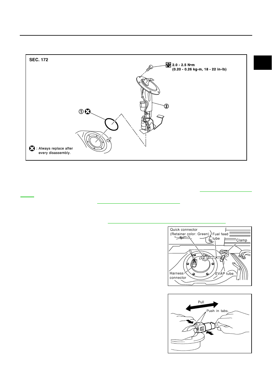
Disconnect harness connector and fuel feed tube.

Disconnect quick connectors of fuel tube as follows.

1.

O-ring

2.

Fuel level sensor unit, fuel filter and 
fuel pump assembly

PBIC0957E

PBIC0958E

SFE562A

FL-4

FUEL LEVEL SENSOR UNIT, FUEL FILTER AND FUEL PUMP ASSEMBLY

NOTE:
The followings are also applied to quick connector of EVAP
tube.

Hold the sides of the connector, push in tubs and pull out the
tube.

If the connector and the tube are stuck together, push and pull
several times until they start to move. Then disconnect them
by pulling.

CAUTION:

Quick connector can be disconnected when the tabs are
completely depressed. Do not twist it more than neces-
sary.

Do not use any tools to disconnect quick connector.

Keep resin tube away from heat. Be especially careful
when welding near the tube.

Prevent acid liquid such as battery electrolyte etc. from
getting on resin tube.

Do not bend or twist resin tube during installation and
disconnection.

Do not remove the remaining retainer on hard tube (or the
equivalent) except when resin tube or retainer is
replaced.

When resin tube or hard tube (or the equivalent) is
replaced, also replace retainer with a new one. 

To keep clean the connecting portion and to avoid dam-
age and foreign materials, cover them completely with
plastic bags or something similar.

6.

Remove fuel level sensor unit, fuel filter and fuel pump assem-
bly.

CAUTION:

Do not bend the float arm during removal. 

Avoid impacts such as falling when handling compo-
nents.

INSPECTION AFTER REMOVAL

Make sure fuel pump strainer is free from foreign materials. If any are found, remove them.

Retainer color: Green

SBIA0504E

PBIC0163E

FUEL LEVEL SENSOR UNIT, FUEL FILTER AND FUEL PUMP ASSEMBLY

FL-5

C

D

E

F

G

H

I

J

K

L

M

A

FL

INSTALLATION

Install in the reverse order of removal.

Set fuel tube connector of fuel level sensor unit facing the right
side of vehicle. Install it by matching the notches on its outer cir-
cumferences and fuel tank.

Tighten the mounting bolts evenly.

CAUTION:

Use the genuine bolts or equivalent.

Connect quick connector as follows.

1.

Check the connection for damage and foreign materials.

2.

Align the connector with the tube, then insert the connector
straight into the tube until a click is heard.

3.

After connecting, make sure that the connection is secure by fol-
lowing the steps below.

a.

Visually confirm that the two retainer tabs are connected to the
connector. 

b.

Pull the tube and the connector to make sure they are securely
connected.

INSPECTION AFTER INSTALLATION

After installing tubes, make sure there is no fuel leakage at connections in the following steps.

Apply fuel pressure to fuel lines with turning ignition switch ON (with engine stopped). Then check for

fuel leaks at connections.

Start the engine and rev it up and check for fuel leaks at connections.

Disassembly and Assembly

ABS004QL

PBIC0959E

SFE562A

1.

Clip

2.

Pressure regulator

3.

Fuel feed hose

4.

Fuel filter

5.

Fuel feed hose

6.

Pump support rubber

7.

Fuel pump

8.

Temperature sensor

9.

Fuel return hose

10. Pressure regulator housing

11. O-ring

12. Fuel level sensor unit

PBIC1151E

FL-6

FUEL LEVEL SENSOR UNIT, FUEL FILTER AND FUEL PUMP ASSEMBLY

DISASSEMBLY

While referring to the diagram, remove components starting from fuel pump.

1.

Pull out fuel level sensor unit, fuel filter and fuel pump assembly.

2.

Remove pump support rubber from fuel level sensor unit, fuel fil-
ter and fuel pump assembly.

3.

Using a screwdriver, disconnect harness connector from fuel
pump.

CAUTION:

Be careful not to damage it.

4.

Remove fuel pump.

5.

Remove fuel filter.

PBIC1152E

PBIC1153E

PBIC1154E

PBIC1155E


Content   ..  549  550  551  552   ..