Infiniti M45 (Y34). Manual - part 546


  Index      Infiniti     Infiniti M45 (Y34) - service repair manual 2004 year


Search            copyright infringement  


Content   ..  544  545  546  547   ..


Infiniti M45 (Y34). Manual - part 546


EXHAUST SYSTEM

EX-3

C

D

E

F

G

H

I

J

K

L

M

A

EX

EXHAUST SYSTEM

PFP:20100

Checking Exhaust System

ABS00A3G

Check exhaust pipes, muffler and mounting for improper attachment,
leaks, cracks, damage or deterioration.

If anything is found, repair or replace damaged parts.

Removal and Installation

ABS00A3H

CAUTION:

Be sure to use genuine exhaust system parts or equivalents which are specially designed for heat
resistance, corrosion resistance, and shape.

Perform the operation with the exhaust system fully cooled down because the system will be hot
just after engine stops. 

Be careful not to cut your hand on the insulator edge.
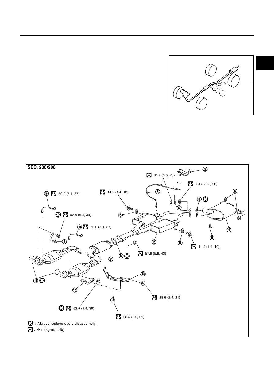
SMA211A

1.

Main muffler

2.

Actuator

3.

Gasket

4.

Ground cable

5.

Cable

6.

Mounting rubber

7.

Exhaust front tube

8.

Bracket

9.

Heated oxygen sensor 2 (bank 2)

PBIC3105E

EX-4

EXHAUST SYSTEM

REMOVAL

1.

Remove cable from exhaust control valve.Refer to 

EX-9, "Removal and Installation"

2.

Remove heated oxygen sensor 2 as follows:
NOTE:
Information for parts installation/disassembly is as follows although the information is not needed in view
of installation/disassembly procedure.

a.

Disconnect harness connector of each heated oxygen sensor 2.

b.

Using heated oxygen sensor wrench (SST), remove both left
and right heated oxygen sensor 2.

Put marks to identify installation positions of each heated oxy-
gen sensor 2.

CAUTION:

Be careful not to damage heated oxygen sensor.

NOTE:
Figure is shown as an example of right bank.

3.

Disconnect each joint and mounting using power tool. 

INSTALLATION

Install in the reverse order of removal.

CAUTION:

Always replace exhaust gaskets with new ones when reassembling.

Discard any heated oxygen sensor which has been dropped from a height of more than 0.5 m (19.7
in) onto a hard surface such as a concrete floor; use a new one. 

Before installing a new heated oxygen sensor, clean exhaust system threads using the heated
oxygen sensor thread cleaner (commercial service tool: J-43897-18 or J-43897-12), and apply anti-
seize lubricant (commercial service tool). 

Do not over torque heated oxygen sensor. Doing so may cause damage to the heated oxygen sen-
sor, resulting in the MIL coming on. 

If the insulator is badly deformed, repair or replace it. If deposits such as mud pile up on the insu-
lator, remove them.

When installing insulator avoid large gaps or interference between insulator and each exhaust
pipe.

Remove deposits and left over gasket material from the sealing surface of each connection. Con-
nect them securely to avoid gas leakage. 

Temporarily tighten mounting nuts on the exhaust manifold side and mounting bolts on the vehi-
cle side. Check each part for unusual interference, and then tighten them to the specified torque. 

When installing each clamp, align the protrusion on insulator with the clamp hole. 

When installing each mounting rubber, avoid twisting or unusual extension in up/down and right/
left directions.

Install mounting rubbers on rear main muffler as shown.       

10.

Heated oxygen sensor 2 (bank 1) 11.

Ring gasket

12. Bracket

13.

Bracket

14.

Gasket

15. Center muffler

PBIC2671E

PBIC0172E

EXHAUST SYSTEM

EX-5

C

D

E

F

G

H

I

J

K

L

M

A

EX

INSPECTION AFTER INSTALLATION

Install in the reverse order of removal paying attention to the followings.

Check clearance between tail tube and bumper is even.

With engine running, check exhaust tube joints for gas leakage and unusual noises.

Check to ensure that mounting brackets and mounting insulators are installed properly and free from
undue stress. Improper installation could result in excessive noise and vibration. 

EX-6

DUAL MODE MUFFLER

DUAL MODE MUFFLER

PFP:20130

Component Parts Location

ABS00A3I

NOTE:
Refer to 

EX-9, "Removal and Installation"

  about Muffler control unit

and Cable.

PBIC0175E

PBIC0177E


Content   ..  544  545  546  547   ..