Infiniti M45 (Y34). Manual - part 531


  Index      Infiniti     Infiniti M45 (Y34) - service repair manual 2004 year


Search            copyright infringement  


Content   ..  529  530  531  532   ..


Infiniti M45 (Y34). Manual - part 531


OIL SEAL

EM-61

C

D

E

F

G

H

I

J

K

L

M

A

EM

OIL SEAL

PFP:00100

Removal and Installation of Valve Oil Seal

ABS004RW

REMOVAL

1.

Remove camshaft relating to valve oil seal to be removed. Refer to 

EM-49, "CAMSHAFT"

 .

2.

Remove adjusting shims and valve lifters. Refer to 

EM-49, "CAMSHAFT"

 .

Correctly identify location where each part is installed. Keep parts in an organized way to avoid mixing
them up.

3.

Turn crankshaft until the cylinder requiring new oil seals is at TDC. This will prevent the valve from drop-
ping into cylinder.

4.

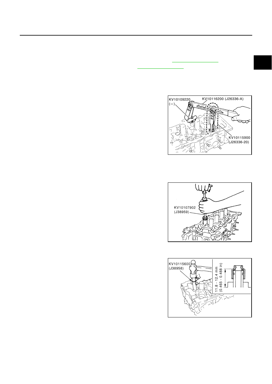
Remove valve collet. 

Compress valve spring with the valve spring compressor,
attachment and adapter (SST). Remove valve collet with
magnetic hand.

CAUTION:

When working, take care not to damage valve lifter holes.

5.

Remove valve spring retainer and valve spring (with valve spring seat).

CAUTION:

Do not remove valve spring seat from valve spring.

6.

Remove valve oil seal using the valve oil seal puller (SST).

INSTALLATION

1.

Apply engine oil on new valve oil seal joint and seal lip.

2.

Install valve oil seal.

Install with the valve oil seal drift (SST) to match dimension in
illustration.

3.

Install in the reverse order of removal.

PBIC2360E

PBIC0072E

PBIC0073E

EM-62

OIL SEAL

Removal and Installation of Front Oil Seal

ABS004RX

REMOVAL

1.

Remove the following parts:

Engine undercover

Drive belt; Refer to 

EM-13, "DRIVE BELTS"

 .

Rear plate cover; Refer to 

EM-25, "OIL PAN AND OIL STRAINER"

 .

Cooling fan; Refer to 

CO-19, "COOLING FAN"

 .

2.

Set the ring gear stopper (SST).

3.

Remove crankshaft pulley with the following procedure: 

a.

Loosen crankshaft pulley bolt.

b.

Pull crankshaft pulley with both hands to remove it.

CAUTION:

Do not remove fixing bolt. Keep loosened fixing bolt in
place to protect removed crankshaft pulley from drop-
ping.

Do not remove balance weight (inner hexagon bolt) at the
front of crankshaft pulley.

4.

Remove front oil seal using a suitable tool.

CAUTION:

Be careful not to damage front cover and oil pump drive
spacer.

INSTALLATION

1.

Install front oil seal onto front cover. 

Apply engine oil on new front oil seal.

Install new front oil seal in the direction shown in the figure.

CAUTION:

Be careful not to scratch or make burrs on circumference
of oil seal.

PBIC1656E

SBIA0358E

SBIA0359E

SEM715A

OIL SEAL

EM-63

C

D

E

F

G

H

I

J

K

L

M

A

EM

Using the front oil seal drift (commercial service tool) or drift
with 54 mm (2.13 in) diameter, force fit the seal until it levels
with the front end surface of front cover.

2.

Install in the reverse order of removal.

SBIA0359E

EM-64

OIL SEAL

Removal and Installation of Rear Oil Seal

ABS004RY

REMOVAL

1.

Remove transmission assembly. Refer to 

AT-331, "TRANSMISSION ASSEMBLY"

 .

a.

Remove drive plate.

Holding crankshaft pulley mounting bolts, lock crankshaft to remove bolts fixing drive plate.

Loosen fixing bolts diagonally.

CAUTION:

Be careful not to damage drive plate. Especially, avoid deforming and damaging of signal plate
teeth (circumference position).

Place the drive plate with signal plate surface facing other than downward.

Keep magnetic materials away from signal plate.

b.

Remove engine rear plate.

2.

Remove rear oil seal using a suitable tool.

CAUTION:

Be careful not to damage crankshaft and oil seal retainer
surface.

INSTALLATION

1.

Install rear oil seal using the rear oil seal drift (commercial service tool).

Apply engine oil on new rear oil seal.

Install new oil seal in the direction shown in the figure.

CAUTION:

Be careful not to scratch or make burrs on circumference
of rear oil seal.

Tap until flattened with front edge of oil seal retainer. Do not
damage or scratch outer circumference of oil seal.

2.

Install in the reverse order of removal.

SBIA0360E

SEM715A

SBIA0360E


Content   ..  529  530  531  532   ..