Infiniti M45 (Y34). Manual - part 491


  Index      Infiniti     Infiniti M45 (Y34) - service repair manual 2004 year


Search            copyright infringement  


Content   ..  489  490  491  492   ..


Infiniti M45 (Y34). Manual - part 491


IGNITION SIGNAL

EC-653

C

D

E

F

G

H

I

J

K

L

M

A

EC

Specification data are reference values and are measured between each terminal and ground.
Pulse signal is measured by COSULT-II.

CAUTION:

Do not use ECM ground terminals when measuring input/output voltage. Doing so may result in dam-
age to the ECM's transistor. Use a ground other than ECM terminals, such as the ground.

: Average voltage for pulse signal (Actual pulse signal can be confirmed by oscilloscope.)

TER-

MINAL 

NO.

WIRE 

COLOR

ITEM

CONDITION

DATA (DC Voltage)

19
21
30
32

W/G
W/R
PU/W
G/R

Ignition signal No. 2
Ignition signal No. 4
Ignition signal No. 6
Ignition signal No. 8
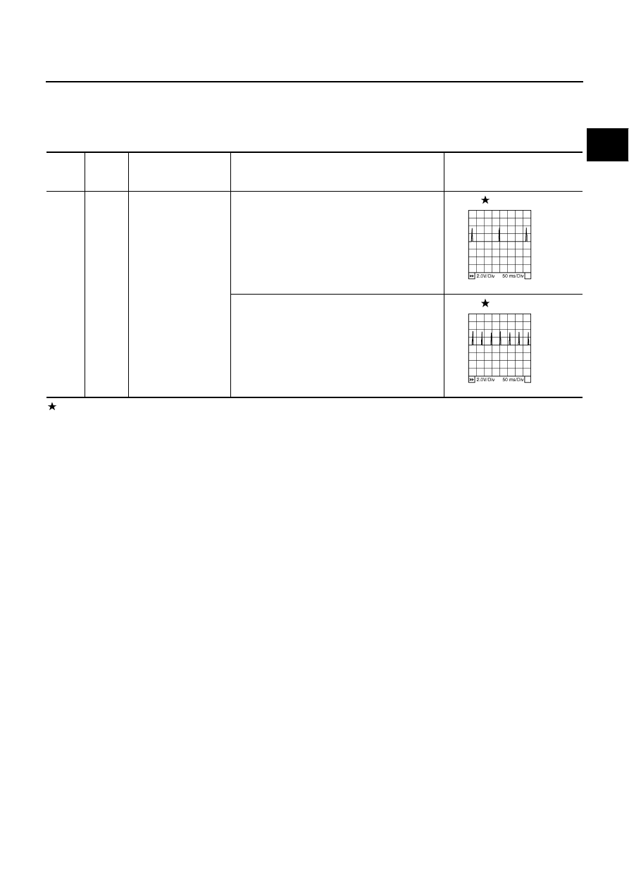
[Engine is running]

Warm-up condition

Idle speed

NOTE:
The pulse cycle changes depending on rpm at idle.

0 - 0.1V

[Engine is running]

Warm-up condition

Engine speed: 2,000 rpm.

0 - 0.2V

PBIB0044E

PBIB0045E

EC-654

IGNITION SIGNAL

TBWA0309E

IGNITION SIGNAL

EC-655

C

D

E

F

G

H

I

J

K

L

M

A

EC

Specification data are reference values and are measured between each terminal and ground.
Pulse signal is measured by COSULT-II.

CAUTION:

Do not use ECM ground terminals when measuring input/output voltage. Doing so may result in dam-
age to the ECM's transistor. Use a ground other than ECM terminals, such as the ground.

: Average voltage for pulse signal (Actual pulse signal can be confirmed by oscilloscope.)

Diagnostic Procedure

ABS002TN

1. 

CHECK ENGINE START

Turn ignition switch OFF, and restart engine.
Is engine running?

Yes or No

Yes (With CONSULT-II)>>GO TO 2.
Yes (Without CONSULT-II)>>GO TO 3.
No

>> GO TO 4.

2. 

CHECK OVERALL FUNCTION

 With CONSULT-II

1.

Perform “POWER BALANCE” in “ACTIVE TEST” mode with
CONSULT-II.

2.

Make sure that each circuit produces a momentary engine
speed drop.

OK or NG

OK

>> INSPECTION END

NG

>> GO TO 11.

TER-

MINAL 

NO.

WIRE 

COLOR

ITEM

CONDITION

DATA (DC Voltage)

18
20
29
31

Y/R
GY
GY/R
L/R

Ignition signal No. 1
Ignition signal No. 3
Ignition signal No. 5
Ignition signal No. 7

[Engine is running]

Warm-up condition

Idle speed

NOTE:
The pulse cycle changes depending on rpm at idle.

0 - 0.1V

[Engine is running]

Warm-up condition

Engine speed: 2,000 rpm.

0 - 0.2V

PBIB0044E

PBIB0045E

PBIB0133E

EC-656

IGNITION SIGNAL

3. 

CHECK OVERALL FUNCTION

 Without CONSULT-II

1.

Let engine idle.

2.

Read the voltage signal between ECM terminals 18, 19, 20, 21,
29, 30, 31, 32 and ground with an oscilloscope.

3.

Verify that the oscilloscope screen shows the signal wave as
shown below.

NOTE:
The pulse cycle changes depending on rpm at idle.

OK or NG

OK

>> INSPECTION END

NG

>> GO TO 11.

4. 

CHECK IGNITION COIL POWER SUPPLY CIRCUIT-I

1.

Turn ignition switch OFF, wait at least 10 seconds and then turn ON.

2.

Check voltage between ECM terminals 163, 166 and ground
with CONSULT-II or tester.

OK or NG

OK

>> GO TO 5.

NG

>> Go to 

EC-133, "POWER SUPPLY AND GROUND CIR-

CUIT"

 .

5. 

CHECK IGNITION COIL POWER SUPPLY CIRCUIT-II

Check voltage between ECM terminal 12 and ground with CON-
SULT-II or tester.

OK or NG

OK

>> GO TO 11.

NG

>> GO TO 6.

PBIB2077E

PBIB0044E

Voltage: Battery voltage

PBIB0135E

Voltage: Battery voltage

PBIB0136E


Content   ..  489  490  491  492   ..