Infiniti M45 (Y34). Manual - part 461
 

  Index      Infiniti     Infiniti M45 (Y34) - service repair manual 2004 year


Search            copyright infringement  


Content   ..  459  460  461  462   ..


Infiniti M45 (Y34). Manual - part 461


DTC P1229 SENSOR POWER SUPPLY

EC-533

C

D

E

F

G

H

I

J

K

L

M

A

EC

Specification data are reference values and are measured between each terminal and ground.

CAUTION:

Do not use ECM ground terminals when measuring input/output voltage. Doing so may result in dam-
age to the ECM's transistor. Use a ground other than ECM terminals, such as the ground.

Diagnostic Procedure

ABS002QC

1. 

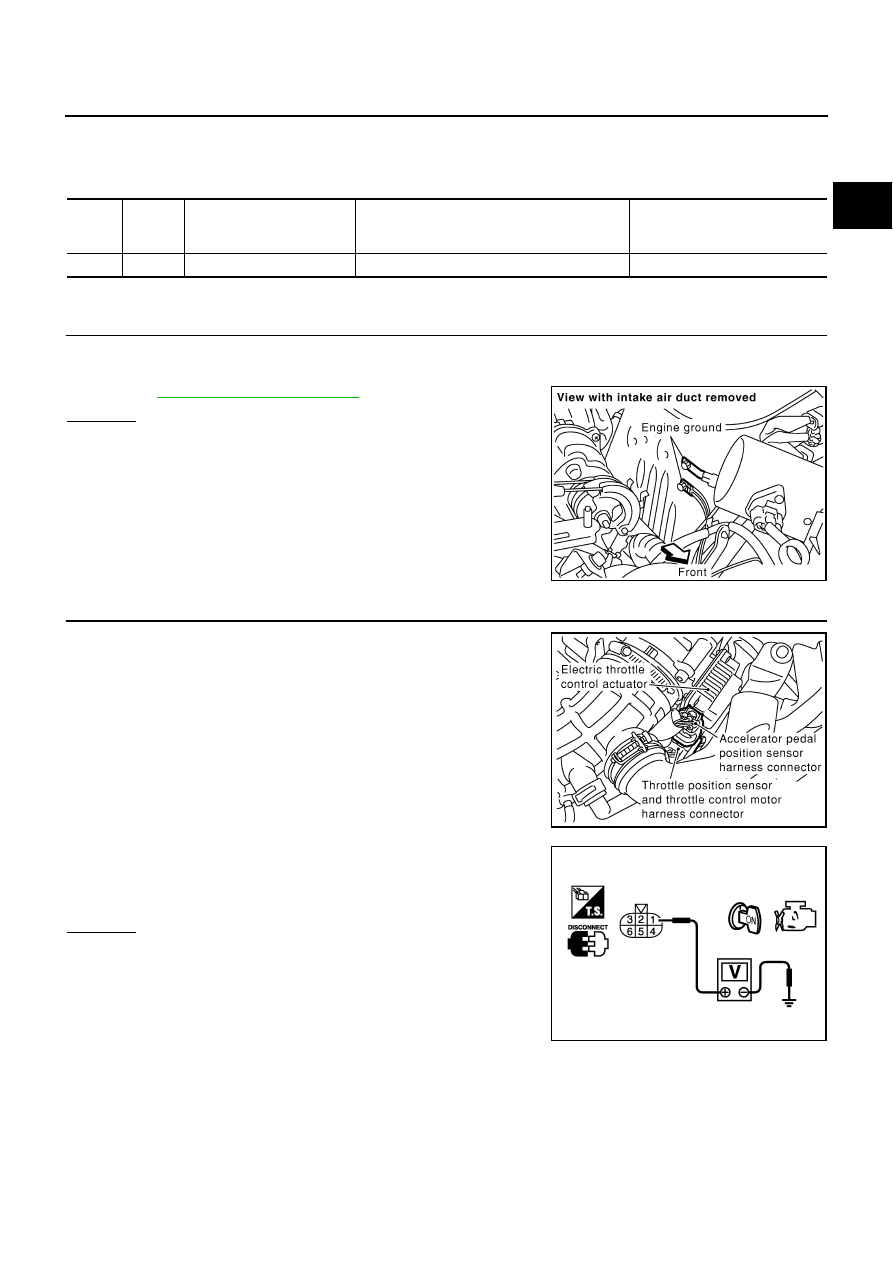
CHECK GROUND CONNECTIONS

1.

Turn ignition switch OFF.

2.

Loosen and retighten two ground screws. 
Refer to 

EC-141, "Ground Inspection"

 .

OK or NG

OK

>> GO TO 2.

NG

>> Repair or replace ground connections.

2. 

CHECK THROTTLE POSITION SENSOR POWER SUPPLY CIRCUIT

1.

Disconnect electric throttle control actuator harness connector.

2.

Turn ignition switch ON.

3.

Check voltage between electric throttle control actuator terminal
1 and ground with CONSULT-II or tester.

OK or NG

OK

>> GO TO 5.

NG

>> GO TO 3.

TER-

MINAL 

NO.

WIRE 

COLOR

ITEM

CONDITION

DATA (DC Voltage)

103

L

Sensor power supply

[Ignition switch: ON]

Approximately 5V

PBIB1118E

PBIB0015E

Voltage: Approximately 5V

PBIB0082E

EC-534

DTC P1229 SENSOR POWER SUPPLY

3. 

CHECK SENSOR POWER SUPPLY CIRCUITS

Check the following.

Harness for short to power and short to ground, between the following terminals.

OK or NG

OK

>> GO TO 4.

NG

>> Repair short to ground or short to power in harness or connectors.

4. 

CHECK COMPONENTS

Check the following.

Accelerator pedal position sensor (Refer to 

EC-620, "Component Inspection"

 .)

Mass air flow sensor (Refer to 

EC-188, "Component Inspection"

 .)

EVAP control system pressure sensor (Refer to 

EC-361, "Component Inspection"

 .)

Power steering pressure sensor (Refer to 

EC-409, "Component Inspection"

 .)

Refrigerant pressure sensor (Refer to 

ATC-86, "COMPONENT INSPECTION"

 )

OK or NG

OK

>> GO TO 7.

NG

>> Replace malfunctioning component.

5. 

CHECK THROTTLE POSITION SENSOR

Refer to 

EC-297, "Component Inspection"

 .

OK or NG

OK

>> GO TO 7.

NG

>> GO TO 6.

6. 

REPLACE ELECTRIC THROTTLE CONTROL ACTUATOR

1.

Replace electric throttle control actuator.

2.

Perform 

EC-44, "Accelerator Pedal Released Position Learning"

 .

3.

Perform 

EC-44, "Throttle Valve Closed Position Learning"

 .

4.

Perform 

EC-44, "Idle Air Volume Learning"

 .

>> INSPECTION END

7. 

CHECK INTERMITTENT INCIDENT

Refer to 

EC-132, "TROUBLE DIAGNOSIS FOR INTERMITTENT INCIDENT"

 .

>> INSPECTION END

ECM terminal

Sensor terminals

Reference Wiring Diagram

103

Electric throttle control actuator terminal 1

EC-532

APP sensor terminal 7

EC-617

MAF sensor terminal 2

EC-177

EVAP control system pressure sensor terminal 1

EC-357

Power steering pressure sensor terminal 1

EC-406

Refrigerant pressure sensor terminal 1

EC-681

DTC P1442 EVAP CONTROL SYSTEM

EC-535

C

D

E

F

G

H

I

J

K

L

M

A

EC

DTC P1442 EVAP CONTROL SYSTEM

PFP:14950

On Board Diagnosis Logic

ABS002VJ

NOTE:
If DTC P0442 is displayed with P1448, perform trouble diagnosis for DTC P1448 first. (See 

EC-558

 .)

This diagnosis detects leaks in the EVAP purge line using vapor pressure in the fuel tank.
The EVAP canister vent control valve is closed to shut the EVAP purge line. The vacuum cut valve bypass
valve will then be opened to clear the line between the fuel tank and the EVAP canister purge volume control
solenoid valve. The EVAP control system pressure sensor can now monitor the pressure inside the fuel tank.
If pressure increases, the ECM will check for leaks in the line between the vacuum cut valve and EVAP canis-
ter purge volume control solenoid valve.

CAUTION:

Use only a genuine NISSAN fuel filler cap as a replacement. If an incorrect fuel filler cap is used,
the MIL may come on.

If the fuel filler cap is not tightened properly, the MIL may come on.

DTC No.

Trouble diagnosis name

DTC detecting condition

Possible cause

P1442
1442

EVAP control system 
small leak detected 
(positive pressure)

EVAP control system has a leak, EVAP 
control system does not operate prop-
erly.

Incorrect fuel tank vacuum relief valve

Incorrect fuel filler cap used

Fuel filler cap remains open or fails to close.

Foreign matter caught in fuel filler cap.

Leak is in line between intake manifold and 
EVAP canister purge volume control solenoid 
valve.

Foreign matter caught in EVAP canister vent 
control valve.

EVAP canister or fuel tank leaks

EVAP purge line (pipe and rubber tube) leaks

EVAP purge line rubber tube bent

Blocked or bent rubber tube to EVAP control sys-
tem pressure sensor

Loose or disconnected rubber tube

EVAP canister vent control valve and the circuit

EVAP canister purge volume control solenoid 
valve and the circuit

Fuel tank temperature sensor

O-ring of EVAP canister vent control valve is 
missing or damaged

Water separator

EVAP canister is saturated with water

EVAP control system pressure sensor

Fuel level sensor and the circuit

Refueling control valve

ORVR system leaks

SEF323U

EC-536

DTC P1442 EVAP CONTROL SYSTEM

Use only a genuine NISSAN rubber tube as a replacement.

DTC Confirmation Procedure

ABS002VK

NOTE:

If DTC P0442 is displayed with P1448, perform trouble diagnosis for DTC P1448 first. (See 

EC-558

.)

If DTC Confirmation Procedure has been previously conducted, always turn ignition switch OFF and wait
at least 10 seconds before conducting the next test.

TESTING CONDITION:

Perform “DTC WORK SUPPORT” when the fuel level is between 1/4 and 3/4 full and vehicle is
placed on flat level surface.

Always perform test at a temperature of 0 to 30

°

C (32 to 86

°

F).

 WITH CONSULT-II

1.

Turn ignition switch ON.

2.

Turn ignition switch OFF and wait at least 10 seconds.

3.

Turn ignition switch ON and select “DATA MONITOR” mode with
CONSULT-II.

4.

Make sure that the following conditions are met.
COOLAN TEMP/S: 0 - 70

°

C (32 - 158

°

F)

INT/A TEMP SE: 0 - 30

°

C (32 - 86

°

F)

5.

Select “EVAP SML LEAK P0442/P1442” of “EVAPORATIVE
SYSTEM” in “DTC WORK SUPPORT” mode with CONSULT-II.
Follow the instruction displayed.

NOTE:
If the engine speed cannot be maintained within the range displayed on the CONSULT-II screen, go to

EC-81, "Basic Inspection"

 .

6.

Make sure that “OK” is displayed.
If “NG” is displayed, refer to 

EC-537, "Diagnostic Procedure"

 .

NOTE:
Make sure that EVAP hoses are connected to EVAP canister
purge volume control solenoid valve properly.

 WITH GST

NOTE:
Be sure to read the explanation of 

EC-60, "Driving Pattern"

  before driving vehicle.

PBIB2643E

PBIB0829E

SEC763C


Content   ..  459  460  461  462   ..