Infiniti M45 (Y34). Manual - part 454
DTC P1148, P1168 CLOSED LOOP CONTROL
EC-505
C
D
E
F
G
H
I
J
K
L
M
A
EC
DTC P1148, P1168 CLOSED LOOP CONTROL
PFP:22690
On Board Diagnosis Logic
ABS002P7
These self-diagnoses have the one trip detection logic.
DTC Confirmation Procedure
ABS002P8
CAUTION:
Always drive vehicle at a safe speed.
NOTE:
If DTC Confirmation Procedure has been previously conducted, always turn ignition switch OFF and wait at
least 10 seconds before conducting the next test.
TESTING CONDITION:
●
Never raise engine speed above 3,000 rpm during the DTC Confirmation Procedure. If the engine
speed limit is exceeded, retry the procedure from step 2.
●
Before performing the following procedure, confirm that battery voltage is more than 11V at idle.
WITH CONSULT-II
1.
Start engine and warm it up to normal operating temperature.
2.
Turn ignition switch OFF and wait at least 10 seconds,
3.
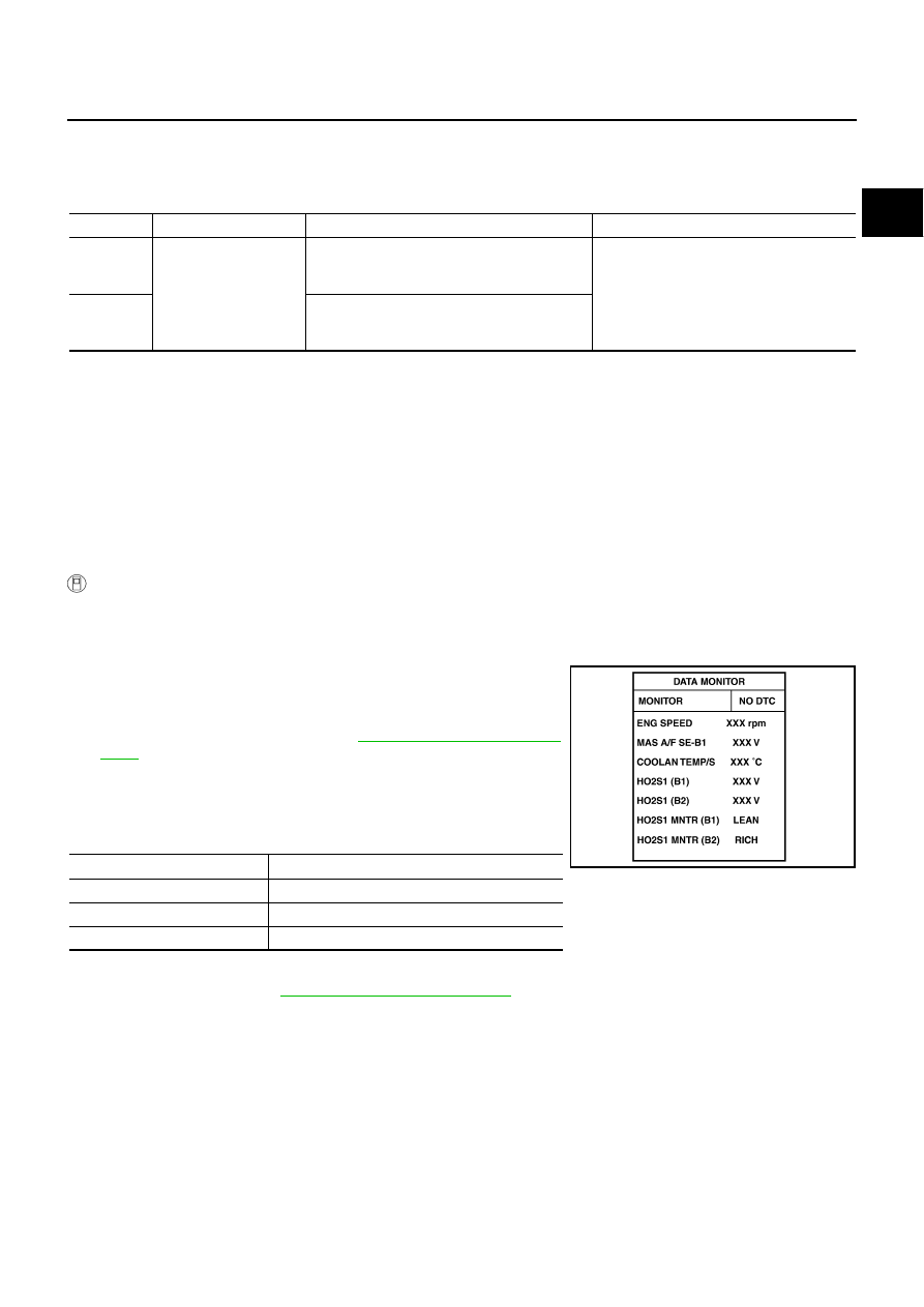
Select “DATA MONITOR” mode with CONSULT-II.
4.
Hold engine speed at 2,000 rpm and check one of the following.
–
“HO2S1 (B1)/(B2)” voltage should go above 0.70V at least once.
–
“HO2S1 (B1)/(B2)” voltage should go below 0.21V at least once.
If the check result is NG, perform
.
If the check result is OK, perform the following step.
5.
Let engine idle at least 5 minutes.
6.
Maintain the following condition at least 50 consecutive sec-
onds.
During this test, P0132 and/or P0152 may be displayed on CONSULT-II screen.
7.
EC-506, "Diagnostic Procedure"
.
DTC No.
Trouble diagnosis name
DTC detecting condition
Possible cause
P1148
1148
(Bank 1)
Closed loop control
function
The closed loop control function for bank 1
does not operate even when vehicle is driving
in the specified condition.
●
The heated oxygen sensor 1 circuit is
open or shorted.
●
Heated oxygen sensor 1
●
Heated oxygen sensor 1 heater
P1168
1168
(Bank 2)
The closed loop control function for bank 2
does not operate even when vehicle is driving
in the specified condition.
B/FUEL SCHDL
4.0 msec or more
ENG SPEED
More than 1,300 rpm
Selector lever
Suitable position
VHCL SPEED SE
More than 71 km/h (44 MPH)
PBIB2025E