Infiniti M45 (Y34). Manual - part 451


  Index      Infiniti     Infiniti M45 (Y34) - service repair manual 2004 year


Search            copyright infringement  


Content   ..  449  450  451  452   ..


Infiniti M45 (Y34). Manual - part 451


DTC P1147, P1167 HO2S2

EC-493

C

D

E

F

G

H

I

J

K

L

M

A

EC

DTC P1147, P1167 HO2S2

PFP:226A0

Component Description

ABS002OY

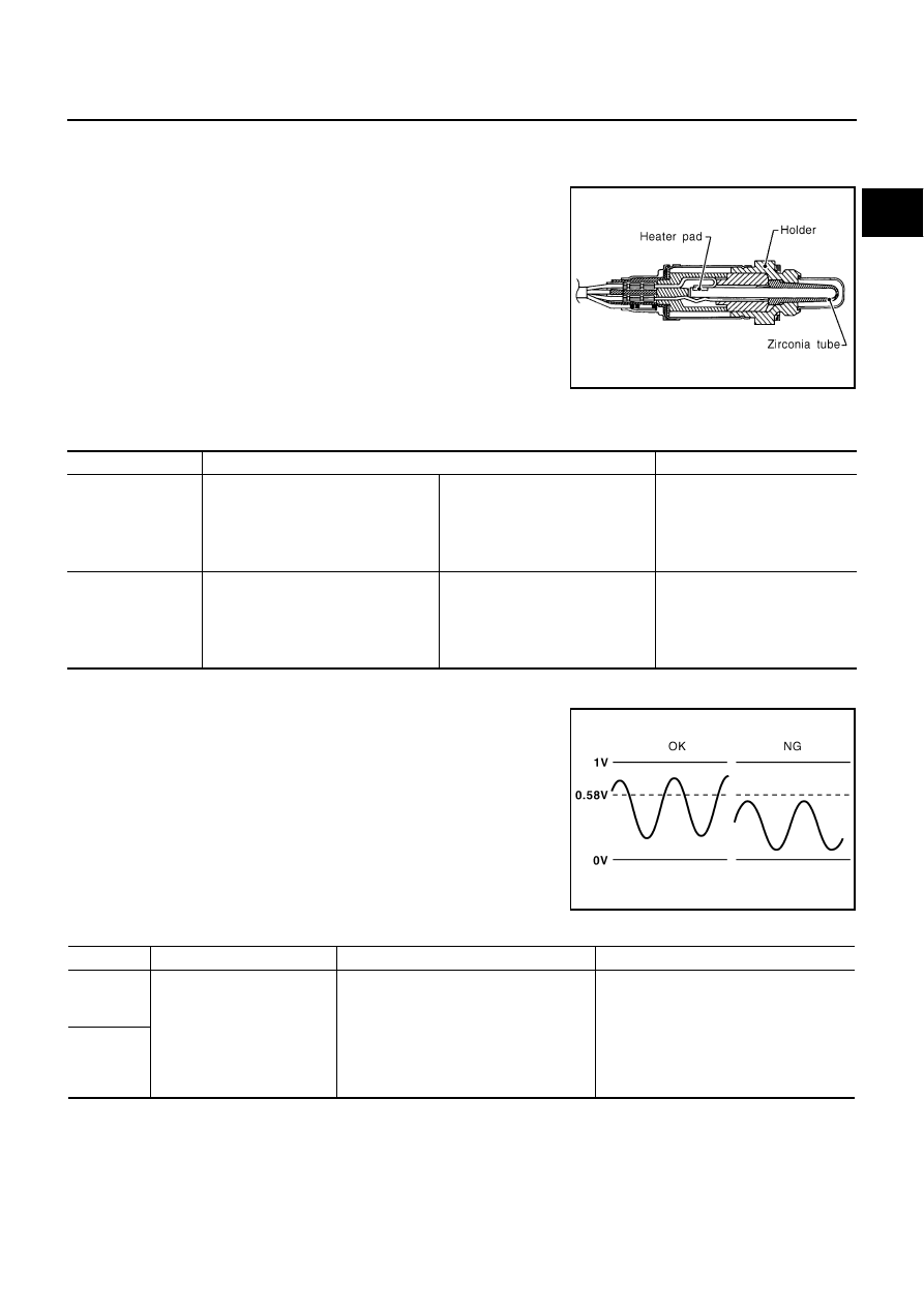
The heated oxygen sensor 2, after three way catalyst (manifold),
monitors the oxygen level in the exhaust gas on each bank.
Even if switching characteristics of the heated oxygen sensor 1 are
shifted, the air-fuel ratio is controlled to stoichiometric, by the signal
from the heated oxygen sensor 2.
This sensor is made of ceramic zirconia. The zirconia generates volt-
age from approximately 1V in richer conditions to 0V in leaner condi-
tions.
Under normal conditions the heated oxygen sensor 2 is not used for
engine control operation.

CONSULT-II Reference Value in Data Monitor Mode

ABS002OZ

Specification data are reference values.

On Board Diagnosis Logic

ABS002P0

The heated oxygen sensor 2 has a much longer switching time
between rich and lean than the heated oxygen sensor 1. The oxygen
storage capacity before the three way catalyst (manifold) causes the
longer switching time. To judge the malfunctions of heated oxygen
sensor 2, ECM monitors whether the maximum voltage of the sensor
is sufficiently high during the various driving condition such as fuel-
cut.

SEF327R

MONITOR ITEM

CONDITION

SPECIFICATION

HO2S2 (B1)
HO2S2 (B2)

Warm-up condition

After keeping the engine speed 
between 3,500 and 4,000 rpm for 1 
minute and at idle for 1 minute 
under no load

Revving engine from idle up to 
3,000 rpm quickly.

0 - 0.3V 

←→

 Approx. 0.6 - 1.0V

HO2S2 MNTR (B1)
HO2S2 MNTR (B2)

Warm-up condition

After keeping the engine speed 
between 3,500 and 4,000 rpm for 1 
minute and at idle for 1 minute 
under no load

Revving engine from idle up to 
3,000 rpm quickly.

LEAN 

←→

 RICH

PBIB1154E

DTC No.

Trouble diagnosis name

DTC detecting condition

Possible cause

P1147
1147
(Bank 1)

Heated oxygen sensor 2 
maximum voltage monitoring

The maximum voltage from the sensor is 
not reached to the specified voltage.

Harness or connectors
(The sensor circuit is open or shorted)

Heated oxygen sensor 2

Fuel pressure

Fuel injector

Intake air leaks

P1167
1167
(Bank 2)

EC-494

DTC P1147, P1167 HO2S2

DTC Confirmation Procedure

ABS002P1

NOTE:
If DTC confirmation Procedure has been previously conducted, always turn ignition switch OFF and wait at
least 10 seconds before conducting the next test.

 WITH CONSULT-II

TESTING CONDITION:
For better results, perform “DTC WORK SUPPORT” at a temperature of 0 to 30 

°

C (32 to 86 

°

F).

1.

Turn ignition switch ON and select “DATA MONITOR” mode with
CONSULT-II.

2.

Start engine and warm it up to the normal operating tempera-
ture.

3.

Turn ignition switch OFF and wait at least 10 seconds.

4.

Start engine and keep the engine speed between 3,500 and
4,000 rpm for at least 1 minute under no load.

5.

Let engine idle for 1 minute.

6.

Make sure that “COOLAN TEMP/S” indicates more than 70

°

C

(158

°

F).

If not, warm up engine and go to next step when “COOLAN
TEMP/S” indication reaches to 70

°

C (158

°

F).

7.

Open engine hood.

8.

Select “HO2S2 (B1) P1147” or “HO2S2 (B2) P1167” of “HO2S2” in “DTC WORK SUPPORT” mode with
CONSULT-II.

9.

Start engine and following the instruction of CONSULT-II.

10. Make sure that “OK” is displayed after touching “SELF-DIAG RESULTS”.

If “NG” is displayed, refer to 

EC-500, "Diagnostic Procedure"

 .

If “CAN NOT BE DIAGNOSED” is displayed, perform the following.

a.

Turn ignition switch OFF and leave the vehicle in a cool place (soak the vehicle).

b.

Return to step 1.

Overall Function Check

ABS002P2

Use this procedure to check the overall function of the heated oxygen sensor 2 circuit. During this check, a 1st
trip DTC might not be confirmed.

 WITH GST

1.

Start engine and warm it up to the normal operating temperature.

2.

Turn ignition switch OFF and wait at least 10 seconds.

3.

Start engine and keep the engine speed between 3,500 and 4,000 rpm for at least 1 minute under no load.

4.

Let engine idle for 1 minute.

5.

Set voltmeter probes between ECM terminal 123 [HO2S2 (B1) signal] or 124 [HO2S2 (B2) signal] and
ground.

SEF189Y

PBIB0819E

DTC P1147, P1167 HO2S2

EC-495

C

D

E

F

G

H

I

J

K

L

M

A

EC

6.

Check the voltage when revving up to 4,000 rpm under no load
at least 10 times.
(Depress and release accelerator pedal as soon as possible.)
The voltage should be above 0.58V at least once during this
procedure.
If the voltage can be confirmed in step 6, step 7 is not nec-
essary.

7.

Keep vehicle at idling for 10 minutes, then check the voltage. Or
check the voltage when coasting from 80 km/h (50 MPH) in D
position.
The voltage should be above 0.58V at least once during this
procedure.

8.

If NG, go to 

EC-500, "Diagnostic Procedure"

 .

PBIB2079E

EC-496

DTC P1147, P1167 HO2S2

Wiring Diagram

ABS002P3

BANK 1

TBWA0276E


Content   ..  449  450  451  452   ..