Infiniti M45 (Y34). Manual - part 439


  Index      Infiniti     Infiniti M45 (Y34) - service repair manual 2004 year


Search            copyright infringement  


Content   ..  437  438  439  440   ..


Infiniti M45 (Y34). Manual - part 439


DTC P1122 ELECTRIC THROTTLE CONTROL FUNCTION

EC-445

C

D

E

F

G

H

I

J

K

L

M

A

EC

2. 

CHECK THROTTLE CONTROL MOTOR GROUND CIRCUIT FOR OPEN AND SHORT

1.

Disconnect ECM harness connector.

2.

Check harness continuity between ECM terminal 153 and ground. 
Refer to Wiring Diagram.

3.

Also check harness for short to power.

OK or NG

OK

>> GO TO 3.

NG

>> Repair open circuit or short to power in harness or connectors.
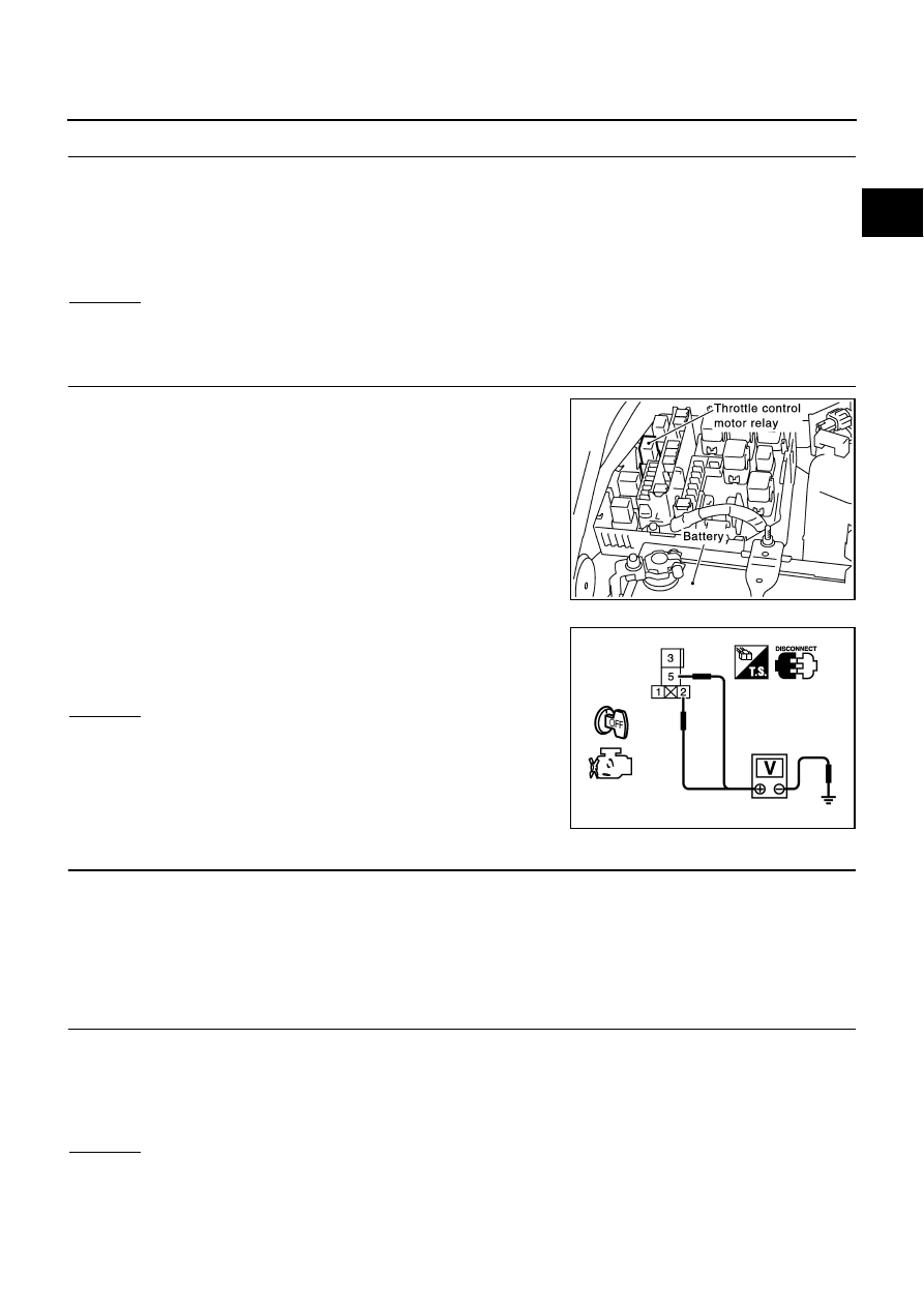
3. 

CHECK THROTTLE CONTROL MOTOR RELAY POWER SUPPLY

1.

Disconnect throttle control motor relay harness connector.

2.

Check voltage between throttle control motor relay terminals 2, 5
and ground with CONSULT-II or tester.

OK or NG

OK

>> GO TO 5.

NG

>> GO TO 4.

4. 

DETECT MALFUNCTIONING PART

Check the following.

15A fuse

Harness for open or short between throttle control motor relay and battery

>> Repair or replace harness or connectors.

5. 

CHECK THROTTLE CONTROL MOTOR RELAY INPUT SIGNAL CIRCUIT FOR OPEN AND SHORT

1.

Check continuity between ECM terminal 157 and throttle control motor relay terminal 3.
Refer to Wiring Diagram.

2.

Also check harness for short to ground and short to power.

OK or NG

OK

>> GO TO 7.

NG

>> GO TO 6.

Continuity should exist.

PBIB1112E

Voltage: Battery voltage

PBIB0575E

Continuity should exist.

EC-446

DTC P1122 ELECTRIC THROTTLE CONTROL FUNCTION

6. 

DETECT MALFUNCTIONING PART

Check the following.

Harness connectors F33, E33

Harness for open or short between ECM and throttle control motor relay

>> Repair open circuit or short to ground or short to power in harness or connectors.

7. 

CHECK THROTTLE CONTROL MOTOR RELAY OUTPUT SIGNAL CIRCUIT FOR OPEN AND SHORT

1.

Check continuity between ECM terminal 26 and throttle control motor relay terminal 1.
Refer to Wiring Diagram.

2.

Also check harness for short to ground and short to power.

OK or NG

OK

>> GO TO 9.

NG

>> GO TO 8.

8. 

DETECT MALFUNCTIONING PART

Check the following.

Harness connectors F34, E34

Harness for open or short between ECM and throttle control motor relay

>> Repair open circuit or short to ground or short to power in harness or connectors.

9. 

CHECK THROTTLE CONTROL MOTOR RELAY

Refer to 

EC-447, "Component Inspection"

 .

OK or NG

OK

>> GO TO 10.

NG

>> Replace throttle control motor relay.

10. 

CHECK THROTTLE CONTROL MOTOR OUTPUT SIGNAL CIRCUIT FOR OPEN OR SHORT

1.

Disconnect electric throttle control actuator harness connector.

2.

Disconnect ECM harness connector.

3.

Check harness continuity between the following terminals.
Refer to Wiring Diagram.

4.

Also check harness for short to ground and short to power.

OK or NG

OK

>> GO TO 11.

NG

>> Repair or replace.

Continuity should exist.

Electric throttle control 

actuator terminal

ECM terminal

Continuity

3

151

Should not exist

154

Should exist

6

151

Should exist

154

Should not exist

PBIB0015E

DTC P1122 ELECTRIC THROTTLE CONTROL FUNCTION

EC-447

C

D

E

F

G

H

I

J

K

L

M

A

EC

11. 

CHECK ELECTRIC THROTTLE CONTROL ACTUATOR VISUALLY 

1.

Remove the intake air duct.

2.

Check if foreign matter is caught between the throttle valve and
the housing.

OK or NG

OK

>> GO TO 12.

NG

>> Remove the foreign matter and clean the electric throttle

control actuator inside.

12. 

CHECK THROTTLE CONTROL MOTOR

Refer to 

EC-447, "Component Inspection"

 .

OK or NG

OK

>> GO TO 13.

NG

>> GO TO 14.

13. 

CHECK INTERMITTENT INCIDENT

Refer to 

EC-132, "TROUBLE DIAGNOSIS FOR INTERMITTENT INCIDENT"

 .

OK or NG

OK

>> GO TO 14.

NG

>> Repair or replace harness or connectors.

14. 

REPLACE ELECTRIC THROTTLE CONTROL ACTUATOR

1.

Replace the electric throttle control actuator.

2.

Perform 

EC-44, "Accelerator Pedal Released Position Learning"

 .

3.

Perform 

EC-44, "Throttle Valve Closed Position Learning"

 .

4.

Perform 

EC-44, "Idle Air Volume Learning"

 .

>> INSPECTION END

Component Inspection

ABS002NL

THROTTLE CONTROL MOTOR RELAY

1.

Apply 12V direct current between relay terminals 1 and 2.

2.

Check continuity between relay terminals 3 and 5.

3.

If NG, replace throttle control motor relay.

PBIB0083E

Conditions

Continuity

12V direct current supply between terminals 
1 and 2

Yes

No current supply

No

PBIB0098E

EC-448

DTC P1122 ELECTRIC THROTTLE CONTROL FUNCTION

THROTTLE CONTROL MOTOR

1.

Disconnect electric throttle control actuator harness connector.

2.

Check resistance between terminals 3 and 6.

3.

If NG, replace electric throttle control actuator and go to next
step.

4.

Perform 

EC-44, "Accelerator Pedal Released Position Learning"

5.

Perform 

EC-44, "Throttle Valve Closed Position Learning"

 .

6.

Perform 

EC-44, "Idle Air Volume Learning"

 .

Remove and Installation

ABS002NM

ELECTRIC THROTTLE CONTROL ACTUATOR

Refer to 

EM-18, "INTAKE MANIFOLD"

 .

Resistance: Approximately 1 - 15 

 [at 25 

°

C (77

°

F)]

PBIB0095E


Content   ..  437  438  439  440   ..