Index Infiniti Infiniti M45 (Y34) - service repair manual 2004 year
Search copyright infringement
Content .. 386 387 388 389 ..
Infiniti M45 (Y34). Manual - part 388
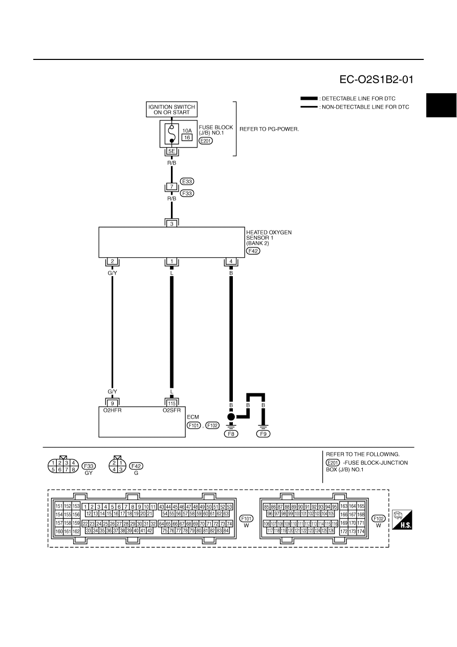
DTC P0134, P0154 HO2S1
EC-241
C
D
E
F
G
H
I
J
K
L
M
A
EC
BANK 2
TBWA0275E