Infiniti M45 (Y34). Manual - part 335
ENGINE CONTROL SYSTEM
EC-29
C
D
E
F
G
H
I
J
K
L
M
A
EC
●
At idle
●
At low battery voltage
●
During acceleration
The knock sensor retard system is designed only for emergencies. The basic ignition timing is programmed
within the anti-knocking zone, if recommended fuel is used under dry conditions. The retard system does not
operate under normal driving conditions. If engine knocking occurs, the knock sensor monitors the condition.
The signal is transmitted to the ECM. The ECM retards the ignition timing to eliminate the knocking condition.
Nissan Torque Demand (NTD) Control System
ABS002VW
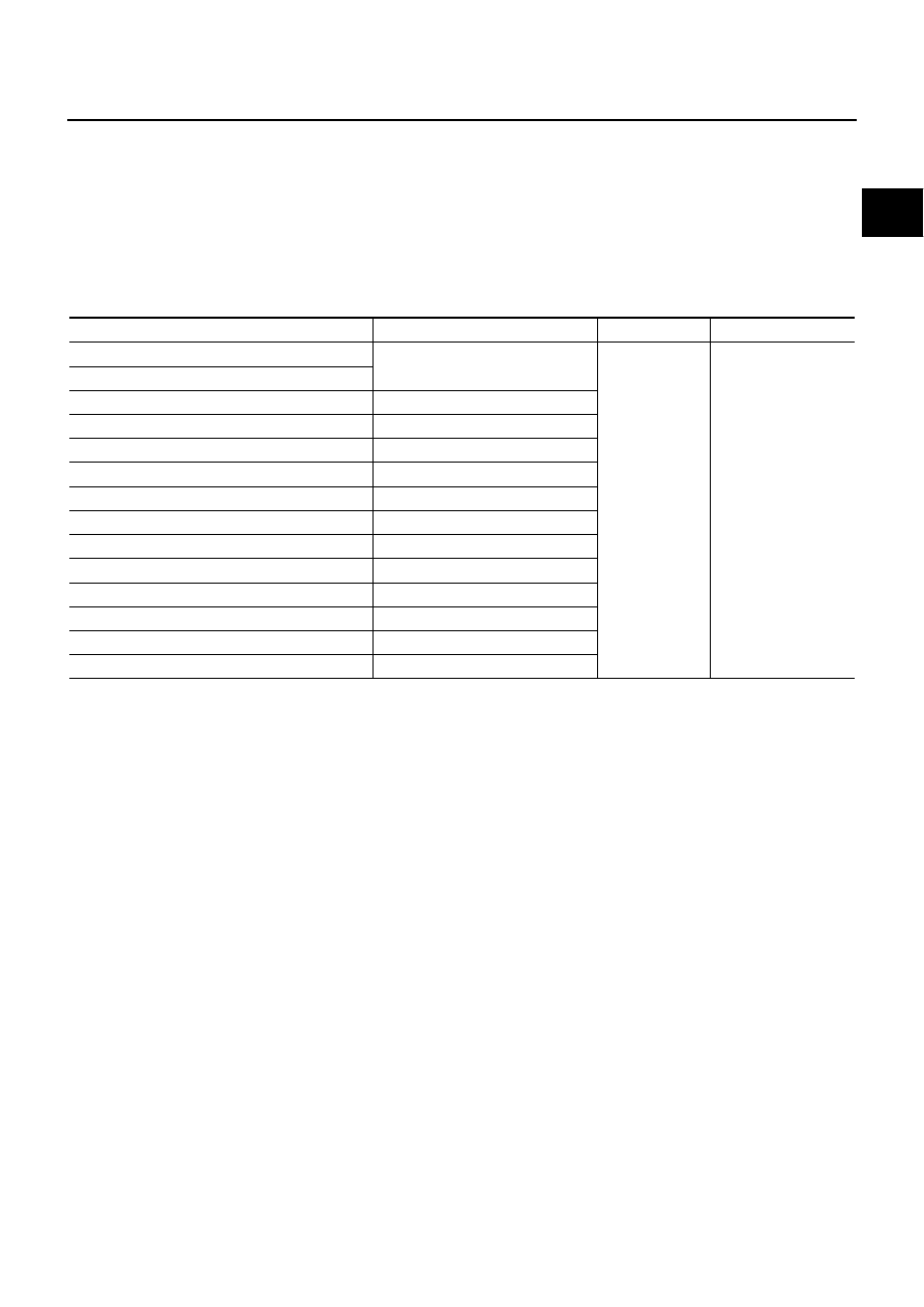
INPUT/OUTPUT SIGNAL CHART
*:This signal is sent to the ECM through CAN communication line.
SYSTEM DESCRIPTION
NTD control system decides the target traction based on the accelerator operation status and the current driv-
ing condition. It then selects the engine torque target by correcting running resistance and atmospheric pres-
sure, and controlling the power-train. Using electric throttle control actuator, it achieves the engine torque
development target which corresponds linearly to the driver's accelerator operation.
Running resistance correction control compares the engine torque estimate value, measured vehicle acceler-
ation, and running resistance on a flat road, and estimates vehicle weight gain and running resistance varia-
tion caused by slopes to correct the engine torque estimate value.
Atmospheric pressure correction control compares the engine torque estimate value from the airflow rate and
the target engine torque for the target traction, and estimates variation of atmospheric pressure to correct the
target engine torque. This system achieves powerful driving without reducing engine performance in the prac-
tical speed range in mountains and high-altitude areas.
Sensor
Input signal to ECM
ECM function
Actuator
Camshaft position sensor (PHASE)
Engine speed
NTD control
Electric throttle con-
trol actuator and fuel
injector
Crankshaft position sensor (POS)
Mass air flow sensor
Amount of intake air
Engine coolant temperature sensor
Engine coolant temperature
Throttle position sensor
Throttle position
Accelerator pedal position sensor
Accelerator pedal position
Park/Neutral position (PNP) switch
Gear position
Power steering pressure sensor
Power steering operation
Battery
Battery voltage
TCM*
A/T control signal
Air conditioner switch*
Air conditioner operation
VDC/TCS/ABS control unit*
VDC/TCS/ABS operation
Wheel sensor*
Vehicle speed
Electrical load*
Electrical load signal