Infiniti M45 (Y34). Manual - part 288
 

  Index      Infiniti     Infiniti M45 (Y34) - service repair manual 2004 year


Search            copyright infringement  


Content   ..  286  287  288  289   ..


Infiniti M45 (Y34). Manual - part 288


THERMOSTAT AND WATER CONTROL VALVE

CO-25

C

D

E

F

G

H

I

J

K

L

M

A

CO

INSPECTION AFTER REMOVAL

●

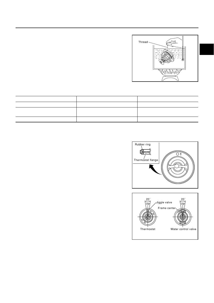
Place a thread so that it is caught in the valves of thermostat and
water control valve. Immerse fully in a container filled with water.
Heat while stirring. (The example in the figure shows the ther-
mostat.) 

●

The valve opening temperature is the temperature at which the
valve opens and falls from the thread. 

●

Continue heating. Check the full-open lift amount.

NOTE:
The full-open lift amount standard temperature for water control
valve is the reference value.

●

 After checking the full-open lift amount, lower the water temper-
ature and check the valve closing temperature.

Standard values

INSTALLATION

Install in the reverse order of removal.

Installation of Thermostat and Water Control Valve

●

Install thermostat and water control valve with the whole circum-
ference of each flange part fit securely inside rubber ring. (The
example in the figure shows thermostat.) 

●

Install thermostat with the jiggle-valve facing upwards. (The
position deviation may be within the range of 

±

10 degrees.)

●

Install water control valve with the up-mark facing up and the
frame center part facing upwards. (The position deviation may
be within the range of 

±

10 degrees.)

SLC252B

Thermostat

Water control valve

Valve opening temperature

80 - 84

°

C (176 - 183

°

 F)     

93.5 - 96.5

°

C (200 - 206

°

F)

Full-open lift amount

More than 10 mm/ 95

°

C

(0.39 in/ 203 

°

F)

More than 8 mm/ 108

°

C

(0.315 in/ 226 

°

 F)

Valve closing temperature

77

°

C (171

°

F)

90

°

C (194

°

 F) 

PBIC0157E

PBIC0158E

CO-26

THERMOSTAT AND WATER CONTROL VALVE

Installation of Water Outlet Pipe and Heater Pipe

First apply a neutral detergent to O-rings, then quickly insert the insertion parts of water outlet pipe and heater
pipe into the installation holes.

INSPECTION AFTER INSTALLATION

●

Check for leaks of the engine coolant using the radiator cap tester adapter [SST: EG17650301 (J33984-
A)] and the radiator cap tester (commercial service tool). Refer to 

CO-9, "CHECKING COOLING SYSTEM

FOR LEAKS"

 .

●

Start and warm up engine. Visually make sure that there is no leaks of engine coolant.

SERVICE DATA AND SPECIFICATIONS (SDS)

CO-27

C

D

E

F

G

H

I

J

K

L

M

A

CO

SERVICE DATA AND SPECIFICATIONS (SDS)

PFP:00030

Standard and Limit

ABS004RC

CAPACITY

THERMOSTAT

WATER CONTROL VALVE

RADIATOR

Unit: kPa (kg/cm

2

 , psi)

Tightening Torque

ABS004RD

                                                                                                                                                                                  Unit: N·m (kg-m, ft-lb)
                                                                                                                                                                                  Unit: N·m (kg-m, in-lb)*

Engine coolant capacity (With reservoir tank at “MAX” level)

Approximately 9.8

 (10-3/8 US qt, 8-5/8 Imp qt)

Reservoir tank engine coolant capacity (at “MAX” level)

0.8 

 (7/8 US qt, 3/4 lmp qt)

Cooling fan fluid capacity

777 m

 (26.3 US floz, 27.4 Imp floz)

Valve opening temperature

80 - 84

°

C (176 - 183

°

F)

Valve lift

More than 10 mm/95

°

C (0.39 in/203

°

F)

Valve closing temperature

77

°

C (171

°

F)

Valve opening temperature

93.5 - 96.5

°

C (200 - 206

°

F)

Valve lift

More than 8 mm/108

°

C (0.315 in/226

°

F)

Valve closing temperature

90

°

C (194

°

F) 

Cap relief pressure

Standard

78 - 98 (0.8 - 1.0, 11 - 14)

Limit

59 (0.6, 9)

Leakage test pressure

157 (1.6, 23)

Radiator mounting bracket
Radiator drain plug
Radiator coolant temperature sensor
Cooling fan shroud
Reservoir tank bracket

3.8 - 4.5 (0.39 - 0.46, 34 - 39)*

0.78 - 1.56 (0.08 - 0.16, 7 - 14)*

4.9 - 9.8 (0.5 - 1.0, 44 - 86)*

3.8 - 4.5 (0.39 - 0.46, 34 - 39)*
3.8 - 4.5 (0.39 - 0.46, 34 - 39)*

Fan
Cooling fan motor
Cooling fan fluid cooler
Fluid hose
Reservoir tank

7.8 - 11.8 (0.8 - 1.2, 70 - 104)*
3.9 - 4.9 (0.40 - 0.49, 35 - 43)*
3.0 - 3.9 (0.31 - 0.39, 27 - 34)*

14.7 - 17.7 (1.5 - 1.8, 11 - 13)
15.7 - 19.6 (1.6 - 1.9, 12 - 14)

Water pump pulley
Water pump

7.2 - 9.2 (0.73 - 0.94, 64 - 81)*

24.5 - 31.4 (2.5 - 3.2, 18 - 23)

Water inlet 
Thermostat housing
Rear water outlet
Water connector
Water suction pipe
Heater pipe

16.7 - 22.6 (1.7 - 2.3, 13 - 16)
16.7 - 22.6 (1.7 - 2.3, 13 - 16)
16.7 - 22.6 (1.7 - 2.3, 13 - 16)
16.7 - 22.6 (1.7 - 2.3, 13 - 16)
16.7 - 22.6 (1.7 - 2.3, 13 - 16)

5.4 - 7.3 (0.55 - 0.75, 48 - 65)*

CO-28

SERVICE DATA AND SPECIFICATIONS (SDS)


Content   ..  286  287  288  289   ..