Infiniti M45 (Y34). Manual - part 280
WHEEL SENSORS
BRC-63
[VDC/TCS/ABS]
C
D
E
G
H
I
J
K
L
M
A
B
BRC
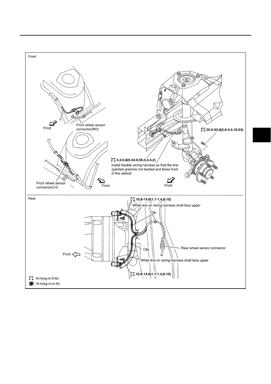
WHEEL SENSORS
PFP:47910
Removal and Installation
AFS000MA
REMOVAL
Pay attention to the following when removing sensor.
CAUTION:
●
As much as possible, avoid rotating sensor when removing it. Pull sensors out without pulling on
sensor harness.
●
Take care to avoid damaging sensor edges or rotor teeth. Remove wheel sensor first before
removing front or rear wheel hub. This is to avoid damage to sensor wiring and loss of sensor
function.
INSTALLATION
Pay attention to the following when installing sensor. Tighten installation bolts and nuts to specified torques.
SFIA0815E