Infiniti M45 (Y34). Manual - part 277


  Index      Infiniti     Infiniti M45 (Y34) - service repair manual 2004 year


Search            copyright infringement  


Content   ..  275  276  277  278   ..


Infiniti M45 (Y34). Manual - part 277


TROUBLE DIAGNOSIS

BRC-51

[VDC/TCS/ABS]

C

D

E

G

H

I

J

K

L

M

A

B

BRC

4. 

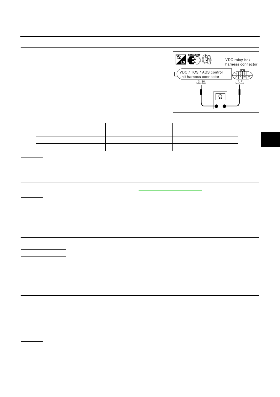
SOLENOID VALVE RELAY HARNESS INSPECTION

1.

Disconnect the VDC/TCS/ABS control unit connector and the
VDC relay box harness connector and the steering angle sensor
connector.

2.

Check the continuity between the VDC/TCS/ABS control unit
connector and the VDC relay box harness connector.

OK or NG

OK

>> GO TO 5.

NG

>> Open or short in harness. Repair or replace the harness.

5. 

SOLENOID VALVE RELAY INSPECTION

Independently check the VDC actuator relay. Refer to 

BRC-56, "VDC RELAY BOX"

 .

OK or NG

OK

>> Replace VDC actuator assembly.

NG

>> Replace the VDC relay box.

Inspection 10 Stop Lamp Switch System

AFS001KE

INSPECTION PROCEDURE

1. 

SELF-DIAGNOSIS RESULT CHECK

Check self-diagnosis results.

Is the above displayed in the self-diagnosis display items?

YES

>> GO TO 2.

NO

>> Inspection End

2. 

CONNECTOR INSPECTION

1.

Disconnect the stop lamp switch connector and VDC/TCS/ABS control unit connector and check the ter-
minals for deformation, disconnection, looseness, and so on. If there is an error, repair or replace the ter-
minal.

2.

Securely reconnect the connectors.

3.

Start engine.

4.

Repeat pumping brake pedal carefully several times, then perform self-diagnosis again.

OK or NG

OK

>> The connector terminal contact is loose, damaged, open or shorted.

NG

>> GO TO 3.

SFIA1935E

VDC/TCS/ABS control unit

(Harness connector E218)

VDC relay box

(Harness connector E56)

Continuity

2 (SB)

5 (SB)

Continuity should exist.

36 (GY/R)

7 (GY/R)

Continuity should exist.

Self-diagnosis results

STOP LAMP SW

BRC-52

[VDC/TCS/ABS]

TROUBLE DIAGNOSIS

3. 

STOP LAMP SWITCH INSPECTION

1.

Turn ignition switch OFF and disconnect the VDC/TCS/ABS
control unit connector.

2.

Check the voltage between the VDC/TCS/ABS control unit har-
ness connector terminal 48 (R/W) and the ground.

OK or NG

OK

>> Connect the connectors and conduct a VDC/TCS/ABS

control unit self-diagnosis.

NG

>> Open or short in harness. Repair or replace the harness.

Inspection 11 VDC/TCS/ABS Control Unit Power and Ground Systems

AFS001KF

INSPECTION PROCEDURE

1. 

SELF-DIAGNOSIS RESULT CHECK

Check self-diagnosis results.

Is the above displayed in the self-diagnosis item?

YES

>> GO TO 2.

NO

>> Inspection End

2. 

CONNECTOR INSPECTION

1.

Disconnect the VDC/TCS/ABS control unit connector and check the terminal for deformation, disconnec-
tion, looseness, and so on. If there is an error, repair or replace the terminal.

2.

Securely reconnect the connector and Re-conduct self-diagnosis.

OK or NG

OK

>> The connector terminal contact is loose, damaged, open or shorted.

NG

>> GO TO 3.

48 (R/W) - Ground

Brake pedal depressed:

Battery voltage (approx. 12V)

Brake pedal not depressed

: Approx. 0V

SFIA1936E

Self-diagnosis results

LOW POWER VOLTAGE

TROUBLE DIAGNOSIS

BRC-53

[VDC/TCS/ABS]

C

D

E

G

H

I

J

K

L

M

A

B

BRC

3. 

VDC/TCS/ABS CONTROL UNIT POWER AND GROUND CIRCUIT INSPECTION

1.

Disconnect the VDC/TCS/ABS control unit connector.

2.

With the ignition switch turned on and off, check the voltage and
continuity between the VDC/TCS/ABS control unit harness con-
nector and the ground.

OK or NG

OK

>> Check the battery (terminal looseness, low voltage, etc.) For any non-standard condition. If any

non-standard condition exists, recharge or replace the battery as necessary.

NG

>> The corresponding harness circuit is open or shorted. Repair the circuit.

SFIA1937E

Signal name

VDC/TCS/ABS control unit

(Harness connector E218)

Ground

Measured value

Power supply

1 (GY)

Battery voltage (Approx. 12V)

SFIA1938E

Signal name

VDC/TCS/ABS control unit

(Harness connector E218)

Ground

Measured value

Ground

27 (B)

Continuity should exist.

28 (B)

Continuity should exist.

29 (B)

Continuity should exist.

33 (B)

Continuity should exist.

BRC-54

[VDC/TCS/ABS]

TROUBLE DIAGNOSIS

Inspection 12 VDC/TCS/ABS Control Unit 2

AFS001KG

INSPECTION PROCEDURE

1. 

SELF-DIAGNOSIS RESULT CHECK

Check self-diagnosis results.

When any item other than “emergency brake” is indicated in self-diagnosis display, follow the instructions
below.

CAUTION:

“Emergency brake” is indicated when control unit itself is detected as an error. If this display item is
indicated, replace control unit.

Is the above displayed in the self-diagnosis display items?

YES

>> Replace the VDC/TCS/ABS control unit and re-conduct the self-diagnosis.

NO

>> Inspection End

Inspection 13 Brake Fluid Level Sensor System

AFS001KH

INSPECTION PROCEDURE

1. 

SELF-DIAGNOSIS RESULT CHECK

1.

Check the brake reservoir tank fluid level. If the level is low, add brake fluid.

2.

Erase the self-diagnosis results and check the self-diagnosis results.

Is the above displayed in the self-diagnosis display items?

YES

>> GO TO 2.

NO

>> Inspection End

2. 

CONNECTOR INSPECTION

1.

Disconnect the brake fluid level sensor connector and VDC/TCS/ABS control unit connector and check
the terminal for deformation, disconnection, looseness, and so on. If there is any non-standard condition,
repair or replace the terminal.

2.

Securely reconnect the connectors and Re-conduct self-diagnosis.

OK or NG

OK

>> The connector terminal contact is loose, damaged, open or shorted.

NG

>> GO TO 3.

Self-diagnosis results

EMERGENCY BRAKE

Self-diagnosis results

BRAKE FLUID LEVEL LOW


Content   ..  275  276  277  278   ..