Infiniti M45 (Y34). Manual - part 232


  Index      Infiniti     Infiniti M45 (Y34) - service repair manual 2004 year


Search            copyright infringement  


Content   ..  230  231  232  233   ..


Infiniti M45 (Y34). Manual - part 232


VEHICLE SECURITY (THEFT WARNING) SYSTEM

BL-153

C

D

E

F

G

H

J

K

L

M

A

B

BL

2. 

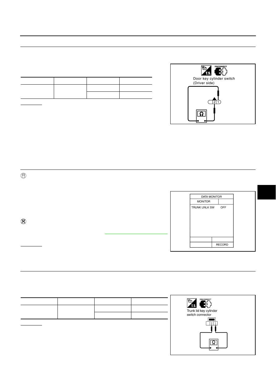
CHECK DOOR KEY CYLINDER SWITCH

1.

Turn ignition switch OFF.

2.

Disconnect front door key cylinder switch (driver side) connector.

3.

Check continuity between front door key cylinder switch (driver
side) terminals.

OK or NG

OK

>> Check the following.

Front door key cylinder switch (driver side) ground cir-
cuit

Harness for open or short between driver door control
unit (LCU01) and front door key cylinder switch (driver side)

NG

>> Replace front door key cylinder switch (driver side).

Diagnostic Procedure 5

AIS001F3

CHECK TRUNK LID KEY UNLOCK SIGNAL

1. 

CHECK TRUNK KEY CYLINDER SWITCH INPUT SIGNAL (UNLOCK SIGNAL)

 With CONSULT

II

Check trunk lid key cylinder switch “TRUNK UNLK SW” in “DATA MONITOR” mode with CONSULT

II.

When key in key cylinder is at “NEUTRAL” position,

When key is “UNLOCK” position,

 Without CONSULT

II

Check trunk lid key cylinder switch in Switch monitor mode.
Refer to Remote keyless entry system, 

BL-79, "SWITCH MONITOR"

.

OK or NG

OK

>> Trunk lid key cylinder switch is OK.

NG

>> GO TO 2.

2. 

CHECK TRUNK KEY CYLINDER SWITCH (UNLOCK SWITCH)

1.

Turn ignition switch OFF.

2.

Disconnect trunk lid key cylinder switch connector.

3.

Check continuity between trunk lid key cylinder switch terminals.

OK or NG

OK

>> Check the following.

Trunk lid key cylinder switch ground circuit

Harness for open or short between trunk lid key cylin-
der switch and BCM

NG

>> Replace trunk lid key cylinder switch.

Connector

Terminal

Condition

Continuity

D12

 2

Neutral/Lock

No

Unlock

Yes

PIIB0204E

TRUNK UNLK SW: OFF

TRUNK UNLK SW: ON

PIIA0356E

Connector

Terminals

Condition

Continuity

B260

1 - 2

Neutral

No

Unlocked

Yes

PIIA0357E

BL-154

VEHICLE SECURITY (THEFT WARNING) SYSTEM

Diagnostic Procedure 6

AIS001F4

CHECK THEFT WARNING HORN ALARM 

1. 

CHECK VEHICLE SECURITY HORN ALARM OPERATION

 With CONSULT

II

Check security horn relay “ALARM RELAY” in “ACTIVE TEST” mode with CONSULT

II.

Perform operation shown on display.

 Without CONSULT

II

1.

Turn ignition switch OFF.

2.

Disconnect BCM connector.

3.

Apply ground to BCM connector E204 terminal 127 (P/L). 

OK or NG

OK

>> Security horn alarm is OK.

NG

>> GO TO 2.

2. 

CHECK SECURITY HORN RELAY

Check security horn relay condition.

OK or NG

OK

>> GO TO 3.

NG

>> Replace security horn relay.

Theft warning horn alarm should operate.

PIIA0358E

Does security horn alarm activate?

PIIA0359E

VEHICLE SECURITY (THEFT WARNING) SYSTEM

BL-155

C

D

E

F

G

H

J

K

L

M

A

B

BL

3. 

CHECK POWER SUPPLY FOR SECURITY HORN RELAY

1.

Turn ignition switch OFF.

2.

Disconnect security horn relay connector.

3.

Check voltage between security horn relay connector E77 terminal 2 (Y/B) and ground.

OK or NG

OK

>> GO TO 4.

NG

>> Check the following.

10A fuse [No. 78, located in the fuse, fusible link and
relay block (J/B)]

Harness for open or short between security horn relay
and fuse

4. 

CHECK SECURITY HORN RELAY CIRCUIT

1.

Disconnect BCM and security horn relay connector.

2.

Check continuity between BCM connector E204 terminal 127 (P/L) and security horn relay connector E77
terminal 1 (P/L).

OK or NG

OK

>> GO TO 5.

NG

>> Repair or replace harness.

5. 

CHECK SECURITY HORN RELAY CIRCUIT

1.

Disconnect security horn connector.

2.

Check continuity between security horn relay connector E77 terminal 3 (P/B) and security horn connector
E30 terminal 1 (P/B).

OK or NG

OK

>> Replace security horn.

NG

>> Repair or replace harness.

2 (Y/B) 

 Ground

: Battery voltage

PIIA2829E

127 (P/L) 

 1 (P/L)

: Continuity should exist.

PIIA2840E

3 (P/B) 

 1 (P/B)

: Continuity should exist.

PIIA2841E

BL-156

VEHICLE SECURITY (THEFT WARNING) SYSTEM

Diagnostic Procedure 7

AIS001F5

CHECK THEFT WARNING HEADLAMP ALARM

1. 

CHECK VEHICLE SECURITY HEADLAMP ALARM OPERATION

 With CONSULT

II

Check headlamp relay “ALARM RELAY” in “ACTIVE TEST” mode with CONSULT

II.

Perform operation shown on display.

 Without CONSULT

II

1.

Disconnect BCM connector.

2.

Apply ground to BCM connector M4 terminal 5 (W/PU). 

OK or NG

OK

>> Headlamp alarm is OK.

NG

>> GO TO 2.

2. 

CHECK HEADLAMP RELAY 1 AND 2

Does headlamp come on when turning lighting switch ON?

YES or NO

YES

>> Check harness for open or short between each headlamp relay and BCM.

NO

>> Check headlamp system. Refer to 

LT-6, "HEADLAMP (FOR USA)"

  or 

LT-44, "HEADLAMP (FOR

CANADA) - DAYTIME LIGHT SYSTEM -"

 .

Theft warning headlamp alarm should operate.

PIIA0362E

Does headlamp alarm activate?

PIIA0363E


Content   ..  230  231  232  233   ..