Infiniti M45 (Y34). Manual - part 214
 

  Index      Infiniti     Infiniti M45 (Y34) - service repair manual 2004 year


Search            copyright infringement  


Content   ..  212  213  214  215   ..


Infiniti M45 (Y34). Manual - part 214


REMOTE KEYLESS ENTRY SYSTEM

BL-81

C

D

E

F

G

H

J

K

L

M

A

B

BL

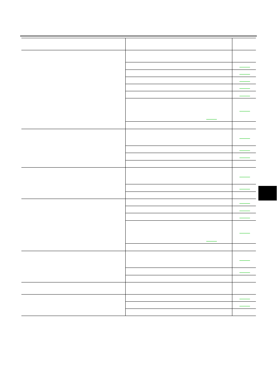
Trunk lid does not open when electronic key trunk opener 
button is continuously pressed.

1.First check the trunk opener cancel switch position is 
“ON”.

–

2. Check electronic key.

BL-82

3. Check trunk lid opener cancel switch.

BL-88

4. Check trunk open signal.

BL-90

5. Check trunk lid opener actuator.

BL-89

6. Check key switch.

BL-84

7. Replace electronic key.

NOTE:
If the result of electronic key check with CONSULT-II is OK, 
electronic key is not malfunctioning. Refer to 

BL-82

 .

BL-99

8. Replace BCM.

–

Hazard reminder does not activate properly when press-
ing lock or unlock button of electronic key.
(Horn reminder is OK.)

1. Check hazard reminder mode*
*: Hazard reminder mode can be changed. First check the 
hazard reminder setting.

BL-75

2. Check hazard function with hazard switch.

BL-96

3. Check hazard reminder operation.

BL-93

4. Replace BCM.

–

Horn reminder does not activate properly when pressing 
lock button of electronic key.
(Hazard reminder is OK.)

1. Check horn reminder mode*
*: Horn reminder mode can be changed. First check the 
horn chirp setting.

BL-75

2. Check security horn operation.

BL-91

3. Replace BCM.

–

Panic alarm (horn and headlamp) does not activate when 
panic alarm button is continuously pressed.
(All other remote keyless entry system function is OK.)

1. Check electronic key.

BL-82

2. Check headlamp function.

BL-96

3. Check key switch.

BL-84

4. Replace electronic key.

NOTE:
If the result of electronic key check with CONSULT-II is OK, 
electronic key is not malfunctioning. Refer to 

BL-82

 .

BL-99

5. Replace BCM.

–

Keyless power window down (open) operation does not 
activate properly.
(All other remote keyless entry system function is OK.)

1. Check power window down operation mode*
*: Power window down operation mode can be changed. 
First check the power window down setting.

BL-75

2. Check power window function.

BL-96

3. Replace BCM.

–

Auto door lock operation does not activate properly.
(All other remote keyless entry system function is OK.)

1. Replace BCM.

–

Map lamp operation does not activate properly.

1. Check map lamp function.

BL-97

2. Check door switch.

BL-85

3. Replace BCM.

–

Symptom

malfunctioning system and reference

Reference 

page

BL-82

REMOTE KEYLESS ENTRY SYSTEM

Check Electronic Key

AIS001DZ

1. 

CHECK ELECTRONIC KEY

 With CONSULT-II

Check Electronic key “LOCK / UNLOCK BUTTON”, “TRUNK BTN-CON” and “PANIC BTN” in “DATA MONI-
TOR” mode with CONSULT-II.

 Without CONSULT-II

Check electronic key in “SWITCH MONITOR” mode. Refer to 

BL-79, "SWITCH MONITOR"

 .

OK or NG

OK

>> Electronic key is OK.

NG

>> GO TO 2.

2. 

CHECK ELECTRONIC KEY ID

 With CONSULT-II

Check electronic key “ID Code” in “WORK SUPPORT” mode with CONSULT-II.
Refer to 

BL-100, "PROCEDURE 2 (WITH CONSULT-II)"

 .

 Without CONSULT-II

Check electronic key “ID Code” in “REMOTE CONTROLLER ID SET UP” mode.
Refer to 

BL-99, "PROCEDURE 1 (WITHOUT CONSULT-II)"

 . 

OK or NG

OK

>> Electronic key was not registered.

NG

>>

●

Check multi remote control receiver.
Refer to 

BL-94, "Check Remote Keyless Entry Receiver"

 .

●

Check electronic key battery.
Refer to 

BL-97, "Electronic Key Battery Replacement"

 .

REMOTE KEYLESS ENTRY SYSTEM

BL-83

C

D

E

F

G

H

J

K

L

M

A

B

BL

Check ACC Power

AIS001PY

1. 

CHECK ACC POWER

 With CONSULT-II

Check ACC power (“ACC ON SW”) in “DATA MONITOR” mode with CONSULT-II.

Without CONSULT-II

Check voltage between BCM connector and ground.

OK or NG

OK

>> ACC power is OK.

NG

>> Check the following.

●

10A fuse [No. 21, located in fuse block (J/B)]

●

Harness for open or short between BCM and fuse.

Monitor item

Condition

ACC ON SW

Ignition switch ACC or ON position

: ON

Ignition switch OFF position

: OFF

PIIA3367E

Item

Connector

Terminal

(Wire color)

Condition

Voltage (V)

(Approx.)

(+)

(–)

BCM

M4

60 (L/OR)

Ground

ACC or ON

Battery voltage

OFF

0

PIIA3438E

BL-84

REMOTE KEYLESS ENTRY SYSTEM

Check Key Switch

AIS001OD

1. 

CHECK KEY SWITCH 

With CONSULT-II

Check key switch “IGN KEY SW” in “DATA MONITOR” mode with
CONSULT-II.

Without CONSULT-II

Check voltage between BCM connector and ground.

OK or NG

OK

>> Key switch is OK.

NG

>> GO TO 2.

2. 

CHECK KEY SWITCH CIRCUIT

1.

Disconnect key switch connector.

2.

Check continuity between BCM connector M4 terminal 69 (PU/W) and key switch connector M64 terminal
4 (PU/W).

3.

Check continuity between BCM connector M4 terminal 69 (PU/
W) and ground.

OK or NG

OK

>> GO TO 3.

NG

>> Repair or replace harness.

Key is inserted in ignition key 
cylinder

: IGN KEY SW ON

Key is removed from ignition 
key cylinder

: IGN KEY SW OFF

PIIA4243E

Item

Connec-

tor

Terminal

(Wire color)

Condition

Voltage (V)

(Approx.)

(+)

(–)

BCM

M4

69 (PU/W)

Ground

Key is inserted

Battery voltage

Key is removed

0

PIIA2820E

69 (PU/W) – 4 (PU/W)

: Continuity should exist.

69 (PU/W) – Ground

: Continuity should not exist.

PIIA2821E


Content   ..  212  213  214  215   ..