Infiniti M45 (Y34). Manual - part 172
AUDIO
AV-21
C
D
E
F
G
H
I
J
L
M
A
B
AV
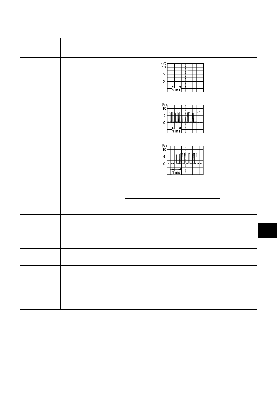
58 (R)
Ground
Communica-
tion signal
(CHG REQ)
Input
ON
Insert/eject
magazine.
CD auto changer
operation is not
possible.
59 (W)
Ground
Communica-
tion signal
(CHG-H/U)
Input
ON
Insert/eject
magazine.
CD auto changer
operation is not
possible.
60 (B)
Ground
Communica-
tion signal
(H/U-CHG)
Output
ON
Press the CD
switch.
CD auto changer
operation is not
possible.
71 (R/L)
Ground
Illumination
signal
Input
OFF
Lighting switch
is ON (1st posi-
tion).
Battery voltage
Audio unit illumi-
nation does not
come on when
lighting switch is
ON (1st position).
Turn lighting
switch OFF.
Approx. 0V
72 (L/B)
Ground
ACC power
Input
ACC
-
Battery voltage
Audio unit opera-
tion is not possi-
ble.
73 (SB)
Ground
Battery power
Input
OFF
-
Battery voltage
Cassette tape
player operation is
not possible.
75 (P/L)
Ground
Radio
antenna amp.
ON signal
Output
ON
-
Approx.10V or more
Receiving status
of radio broadcast
becomes bad.
76 (SB)
Ground
Illumination
control signal
Input
ON
Illumination con-
trol switch is
operated by
lighting switch in
1st position.
Changes between approx. 0 and
approx. 12V.
Audio unit illumi-
nation cannot be
controlled.
78
-
Shield
(Audio sound
signal)
-
-
-
-
-
Terminal No.
Item
Signal
input/
output
Condition
Voltage
Example of symp-
tom
+
-
Ignition
switch
Operation
SKIA0196E
SKIA0197E
SKIA0198E