Infiniti M45 (Y34). Manual - part 149


  Index      Infiniti     Infiniti M45 (Y34) - service repair manual 2004 year


Search            copyright infringement  


Content   ..  147  148  149  150   ..


Infiniti M45 (Y34). Manual - part 149


TROUBLE DIAGNOSIS

ATC-81

C

D

E

F

G

H

I

K

L

M

A

B

ATC

SYSTEM DESCRIPTION

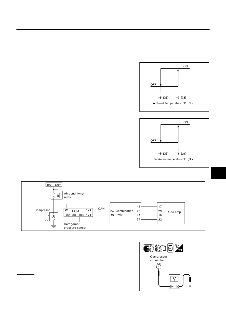
Auto amp. controls compressor operation by ambient temperature, intake air temperature and signal from
ECM.

Low Temperature Protection Control

Auto amp. will turn compressor ON or OFF as determined by a signal detected by ambient sensor and intake
sensor.
When ambient temperatures are higher than 

2

°

C (28

°

F), the com-

pressor turns ON. The compressor turns OFF when ambient temper-
atures are lower than 

5

°

C (23

°

F).

When intake air temperatures are higher than 1

°

C (34

°

F), the com-

pressor turns ON. The compressor turns OFF when intake air tem-
peratures are lower than 

5

°

C (23

°

F).

DIAGNOSTIC PROCEDURE FOR MAGNET CLUTCH

SYMPTOM: Magnet clutch does not engage when AUTO switch is ON.

1. 

CHECK POWER SUPPLY FOR COMPRESSOR

1.

Disconnect compressor harness connector.

2.

Start engine and AUTO switch ON.

3.

Check voltage between compressor (magnet clutch) harness
connector F2 terminal 1 (Y/R) and ground.

OK or NG

OK

>> GO TO 2.

NG

>> GO TO 3.

RHA094GB

SJIA0267E

RJIA1297E

1 – Ground

: Battery voltage

RJIA3035E

ATC-82

TROUBLE DIAGNOSIS

2. 

CHECK MAGNET CLUTCH CIRCUIT

Check operation sound when applying battery voltage direct current
to terminal.

OK or NG

OK

>> Repair harness or connector.

NG

>> Replace magnet clutch. Refer to 

ATC-138, "Removal

and Installation of Compressor Clutch"

 . 

3. 

CHECK CIRCUIT CONTINUITY BETWEEN A/C RELAY AND COMPRESSOR

1.

Turn ignition switch OFF.

2.

Disconnect A/C relay.

3.

Check continuity between compressor (magnet clutch) harness
connector F2 terminal 1 (Y/R) and A/C relay harness connector
E3-2 terminal 3 (Y/R).

OK or NG

OK

>> Check harness for short. And GO TO 4.

NG

>> Repair harness or connector.

4. 

CHECK POWER SUPPLY FOR A/C RELAY

1.

Turn ignition switch ON.

2.

Check voltage between A/C relay harness connector E3-2 termi-
nals 2, 5 and ground.

OK or NG

OK

>> GO TO 5.

NG

>> Check power supply circuit and 10A fuse [No. 51 

located in the fuse, fusible link and relay block (J/B)]. 
Refer to 

PG-64, "FUSE, FUSIBLE LINK AND RELAY 

BLOCK (J/B)"

 .

If OK, check for open circuit in wiring harness. Repair or replace if necessary.

If NG, replace fuse and check wiring harness for short circuit. Repair or replace if necessary.

5. 

CHECK A/C RELAY AFTER DISCONNECTING IT

Refer to 

ATC-86, "A/C Relay"

 .

OK or NG

OK

>> GO TO 6.

NG

>> 1. Replace A/C relay.

2. Go to 

ATC-50, "FUNCTION CONFIRMATION PROCEDURE"

  and perform self-diagnosis

STEP-4. Confirm that magnet clutch operation is usual.

RJIA2005E

1 – 3

: Continuity should exist.

RJIA3036E

2, 5 – Ground

: Battery voltage

RJIA3037E

TROUBLE DIAGNOSIS

ATC-83

C

D

E

F

G

H

I

K

L

M

A

B

ATC

6. 

CHECK COIL SIDE CIRCUIT OF A/C RELAY

1.

Turn ignition switch OFF.

2.

Reconnect A/C relay.

3.

Turn ignition switch ON.

4.

Check voltage between ECM harness connector F101 terminal
24 (G/B) and ground.

OK or NG

OK

>> GO TO 8.

NG

>> GO TO 7.

7. 

CHECK CIRCUIT CONTINUITY BETWEEN ECM AND A/C RELAY

1.

Turn ignition switch OFF.

2.

Disconnect A/C relay connector and ECM connector.

3.

Check continuity between ECM harness connector F101 termi-
nal 24 (G/B) and A/C relay harness connector E3-2 terminal 1
(G/B).

OK or NG

OK

>> Replace A/C relay.

NG

>> Repair harness or connector.

8. 

CHECK VOLTAGE FOR COMBINATION METER (FAN ON SIGNAL)

1.

Turn ignition switch ON.

2.

Check voltage between auto amp. harness connector M120 ter-
minal 29 (SB) and ground.

OK or NG

OK

>> GO TO 9.

NG

>> GO TO 12.

24 – Ground

: Battery voltage

RJIA3038E

24 – 1

: Continuity should exist.

RJIA3039E

Terminals

Condition

Voltage

(+)

(-)

Auto amp. 

connector

Terminal No.

(Wire color)

M120

29 (SB)

Ground

AUTO switch: ON 
(Blower motor operates.)

Approx. 0V

OFF switch: ON 
(A/C system: OFF)

Approx. 5V

RJIA3040E

ATC-84

TROUBLE DIAGNOSIS

9. 

CHECK VOLTAGE FOR COMBINATION METER (COMPRESSOR ON SIGNAL)

Check voltage between auto amp. harness connector M120 terminal
22 (Y/B) and ground.

OK or NG

OK

>> GO TO 10.

NG

>> GO TO 13.

10. 

CHECK VOLTAGE FOR COMBINATION METER (COMPRESSOR FEED BACK SIGNAL)

1.

Start engine and AUTO switch ON.

2.

Check voltage between auto amp. harness connector M119 ter-
minal 18 (OR) and ground.

OK or NG

OK

>> GO TO 11.

NG

>> GO TO 14.

11. 

CHECK REFRIGERANT PRESSURE SENSOR CIRCUIT

Refer to 

EC-680, "REFRIGERANT PRESSURE SENSOR"

 .

OK or NG

OK

>> INSPECTION END

NG

>> Repair or replace the malfunctioning part(s).

12. 

CHECK CIRCUIT CONTINUITY BETWEEN COMBINATION METER AND AUTO AMP.

1.

Turn ignition switch OFF.

2.

Disconnect combination meter and auto amp. connector.

3.

Check continuity between combination meter harness connector
M41 terminal 23 (SB) and auto amp. harness connector M120
terminal 29 (SB).

OK or NG

OK

>> Replace auto amp.

NG

>> Repair harness or connector.

Terminals

Condition

Voltage

(+)

(-)

Auto amp. 

connector

Terminal No.

(Wire color)

M120

22 (Y/B)

Ground

AUTO switdh: ON
(Blower motor operates.)

Approx. 0V

OFF switch: ON
(A/C system: OFF)

Approx. 5V

RJIA3041E

Terminals

Condition

Voltage

(+)

(-)

Auto amp. 

connector

Terminal No.

(Wire color)

M119

18 (OR)

Ground

A/C switch: ON

Approx. 0V

A/C switch: ON
(When the refrigerant 
pressure sensor connector 
is disconnected)

Approx. 5V

RJIA3042E

23 – 29

: Continuity should exist.

RJIA1298E


Content   ..  147  148  149  150   ..