Infiniti M45 (Y34). Manual - part 141


  Index      Infiniti     Infiniti M45 (Y34) - service repair manual 2004 year


Search            copyright infringement  


Content   ..  139  140  141  142   ..


Infiniti M45 (Y34). Manual - part 141


TROUBLE DIAGNOSIS

ATC-49

C

D

E

F

G

H

I

K

L

M

A

B

ATC

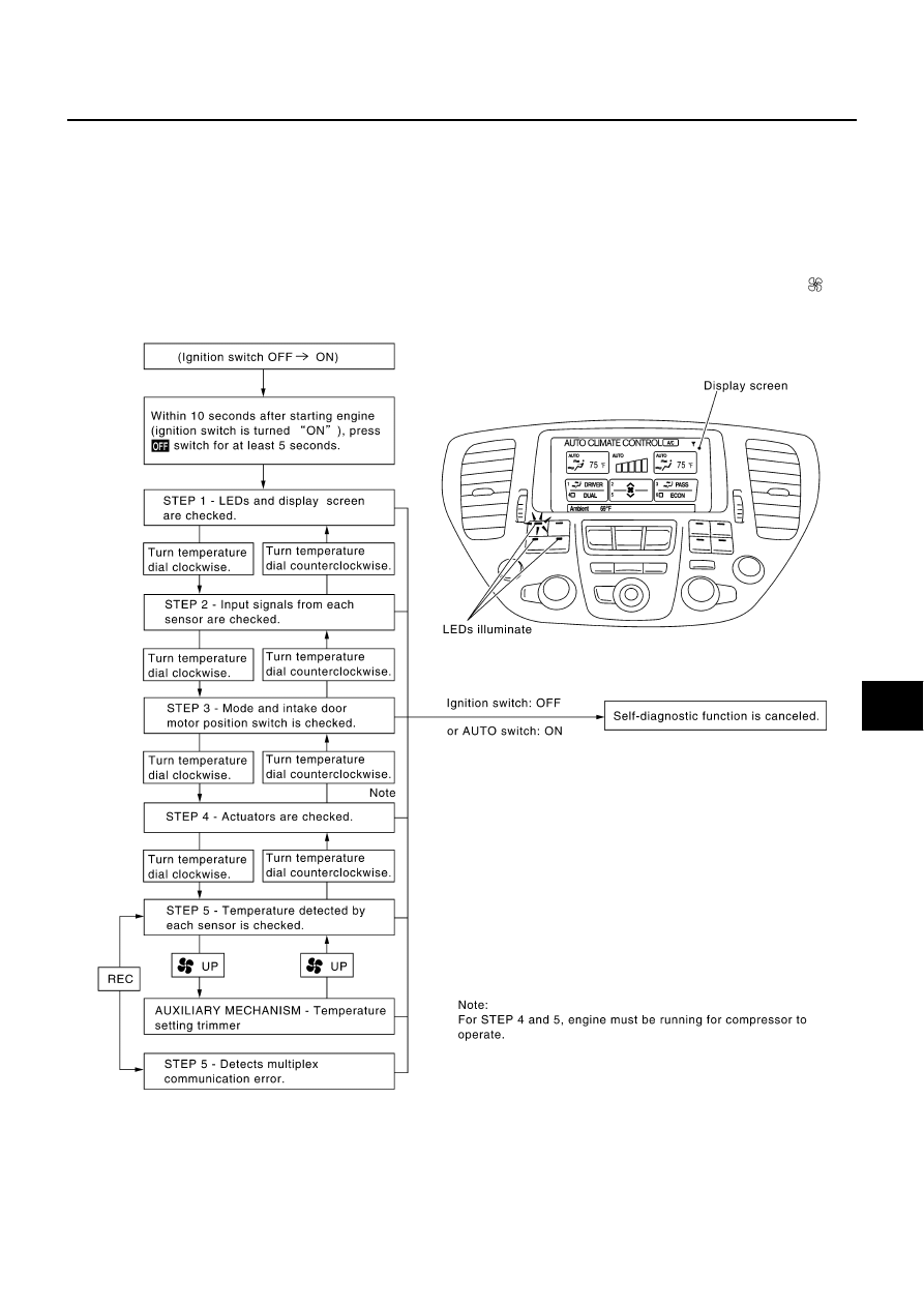
Self-Diagnosis Function

AJS000C6

DESCRIPTION

The self-diagnostic system diagnoses sensors, door motors, blower motor, etc. by system line. Refer to appli-
cable sections (items) for details. Shifting from normal control to the self-diagnostic system is accomplished by
starting the engine (turning the ignition switch ON) and pressing OFF switch for at least 5 seconds. The OFF
switch must be pressed within 10 seconds after starting the engine (ignition switch is turned ON). This system
will be canceled by   either pressing AUTO switch or turning the ignition switch OFF. Shifting from one step to
another is accomplished by means of   turning temperature dial, as required.
Additionally shifting from STEP-5 to AUXILIARY MECHANISM is accomplished by means of pushing  (fan)
UP switch.

RJIA1268E

ATC-50

TROUBLE DIAGNOSIS

FUNCTION CONFIRMATION PROCEDURE

1. 

SET IN SELF-DIAGNOSTIC MODE

1.

Turn ignition switch ON.

2.

Set in self-diagnostic mode as follows. Within 10 seconds after starting engine (ignition switch is turned
ON.), press OFF switch for at least 5 seconds.

CAUTION:

If battery voltage drops below 12V during diagnosis step-3, actuator speed becomes slower and
as a result, the system may generate an error even when operation is normal. To avoid this, start
engine before performing this diagnosis.

>> GO TO 2.

2. 

STEP-1: LEDS AND DISPLAY ARE CHECKED

Check LED illumination and display screen.

OK or NG

OK

>> GO TO 3.

NG

>> Malfunctioning OFF switch, LED or auto amp. Refer to 

ATC-98, "Self-Diagnosis"

 .

3. 

CHECK TO ADVANCE SELF-DIAGNOSIS STEP-2

Turn the temperature dial (driver side) clockwise.

Advance to self-diagnosis STEP-2?

YES

>> GO TO 4.

NO

>> Replace multifunction switch. (Temperature dial malfunctions.)

4. 

CHECK TO RETURN SELF-DIAGNOSIS STEP-1

Turn the temperature dial (driver side) counterclockwise.

Return to self-diagnosis STEP-1?

YES

>> GO TO 5.

NO

>> Replace multifunction switch. (Temperature dial malfunctions.)

RJIA1565E

RJIA1269E

TROUBLE DIAGNOSIS

ATC-51

C

D

E

F

G

H

I

K

L

M

A

B

ATC

5. 

STEP-2: SENSOR CIRCUITS ARE CHECKED FOR OPEN OR SHORT CIRCUIT

Turn the temperature dial (driver side) clockwise.

Does code No. 20 appear on the display?

YES

>> GO TO 6.

NO

>> GO TO 14.

6. 

STEP-3: MODE DOOR AND INTAKE DOOR POSITIONS ARE CHECKED

Turn the temperature dial (driver side) clockwise.

Does code No. 30 appear on the display?

YES

>> GO TO 7.

NO

>> GO TO 15.

7. 

STEP-4: OPERATION OF EACH ACTUATOR IS CHECKED

1.

Turn the temperature dial (driver side) clockwise.

2.

Press

(DEF) switch, code No. of each actuator test is indi-

cated on the display.

>> GO TO 8.

RJIA0219E

RJIA0220E

RJIA0221E

ATC-52

TROUBLE DIAGNOSIS

8. 

CHECK ACTUATORS

Refer to the following chart and confirm discharge air flow, air temperature, blower motor voltage and   com-
pressor operation.

Checks must be made visually, by listening to any noise, or by touching air outlets with your hand, etc. for
improper operation.
OK or NG

OK

>> GO TO 9.

NG

>>

Air outlet does not change.
Go to Mode Door Motor Circuit. Refer to 

ATC-66, "Mode Door Motor Circuit"

 .

Intake door does not change.
Go to Intake Door Motor Circuit. Refer to 

ATC-72, "Intake Door Motor Circuit"

 .

Blower motor operation is malfunctioning.
Go to Blower Motor Circuit. Refer to 

ATC-75, "Blower Motor Circuit"

 .

Magnet clutch does not engage.
Go to Magnet Clutch Circuit Refer to 

ATC-80, "Magnet Clutch Circuit"

 .

Discharge air temperature does not change.
Go to Air Mix Door Motor Circuit. Refer to 

ATC-69, "Air Mix Door Motor Circuit"

 .

RJIA1270E

41

42

43

44

45

46

47

48

Mode door position
(Driver side)

VENT

(B/L 

OPEN)

VENT

(B/L 

SHUT)

B/L1

(B/L 

SHUT)

B/L1

(B/L 

OPEN)

B/L2

FOOT

D/F

DEF

Mode door position
(Passenger side)

VENT

(B/L 

OPEN)

VENT

(B/L 

SHUT)

B/L1

(B/L 

SHUT)

B/L1

(B/L 

OPEN)

B/L2

FOOT1

FOOT2

DEF

Intake door position

REC

REC

REC

20% FRE

20% FRE

FRE

FRE

FRE

Air mix door position

FULL 

COLD

FULL 

COLD

FULL 

COLD

FULL HOT

FULL HOT

FULL HOT

FULL HOT

FULL HOT

Blower motor duty ratio

37%

37%

91%

65%

65%

65%

65%

91%

Compressor

ON

ON

ON

OFF

OFF

OFF

ON

ON

Electronic control valve 
(ECV) duty ratio

100%

50%

100%

0%

0%

0%

50%

100%


Content   ..  139  140  141  142   ..