Infiniti M45 (Y34). Manual - part 109


  Index      Infiniti     Infiniti M45 (Y34) - service repair manual 2004 year


Search            copyright infringement  


Content   ..  107  108  109  110   ..


Infiniti M45 (Y34). Manual - part 109


ON-VEHICLE SERVICE

AT-321

D

E

F

G

H

I

J

K

L

M

A

B

AT

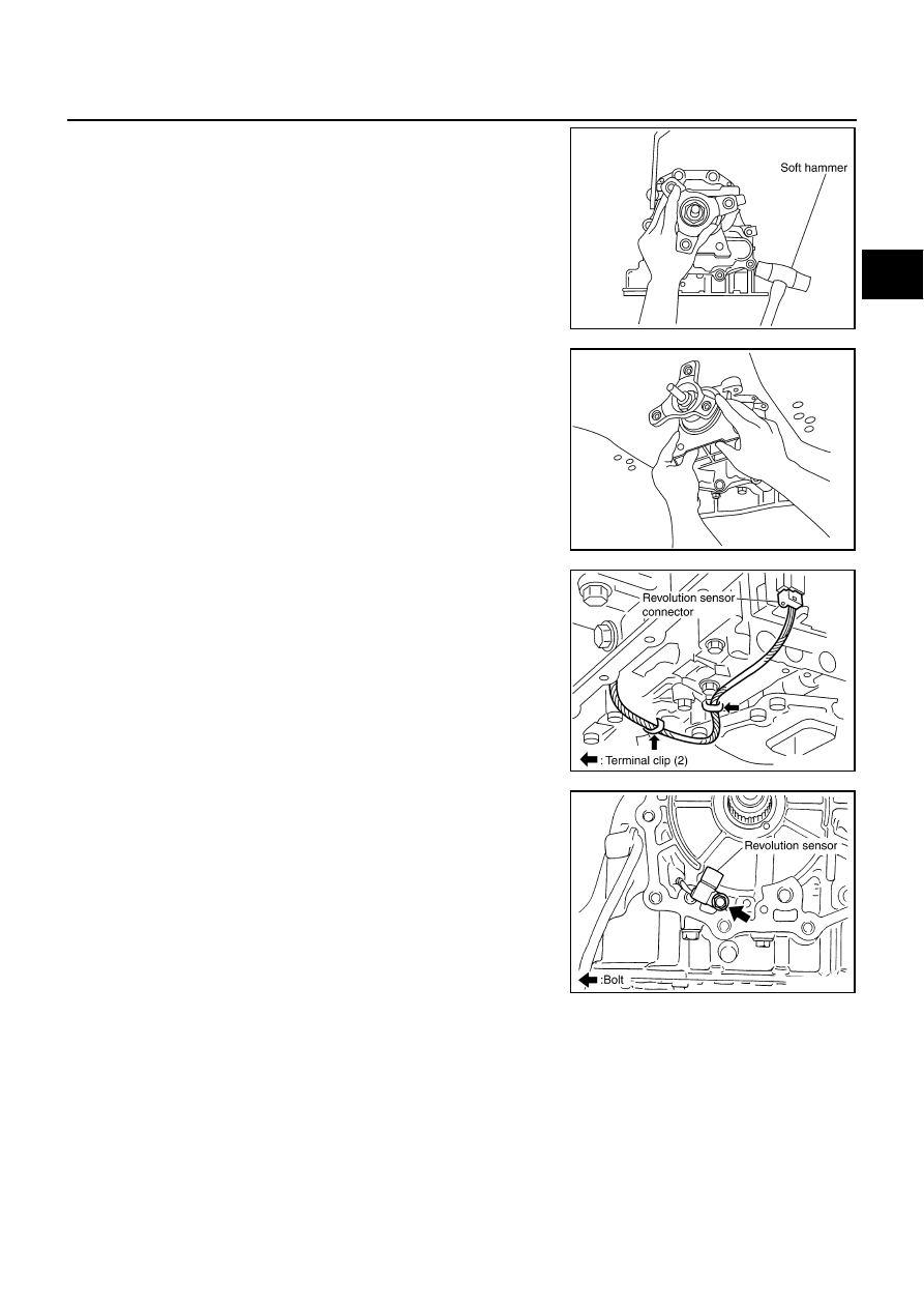
12. Tap output shaft & companion flange complement with a soft

hammer.

13. Remove output shaft & companion flange complement from

transmission assembly. (With needle bearing)

14. Remove revolution sensor connector.

15. Straighten terminal clips to free revolution sensor harness then

remove terminal clips.

16. Remove revolution sensor from transmission assembly.

CAUTION:

Do not subject it to impact by dropping or hitting it.

Do not disassemble.

Do not allow metal filings, etc. to get on the sensor's front
edge magnetic area.

Do not place in an area affected by magnetism.

SCIA4109E

SCIA3968J

SCIA3969E

SCIA3997E

AT-322

ON-VEHICLE SERVICE

INSTALLATION

CAUTION:

After completing installation, check A/T fluid leakage and A/T fluid level. Refer to 

AT-14, "Changing A/

T Fluid"

 , 

AT-14, "Checking A/T Fluid"

 .

1.

Install revolution sensor in transmission assembly.

CAUTION:

Do not subject it to impact by dropping or hitting it.

Do not disassemble.

Do not allow metal filings, etc. to get on the sensor's front
edge magnetic area.

Do not place in an area affected by magnetism.

2.

Connect revolution sensor connector.

3.

Securely fasten revolution sensor harness with terminal clips.

4.

Apply recommended sealant (Genuine Anaerobic Liquid Gasket
or equivalent. Refer to 

GI-46, "Recommended Chemical Prod-

ucts and Sealants"

 .) to output shaft & companion flange com-

plement as shown in the figure.

CAUTION:

Completely remove all moisture, oil and old sealant, etc.
from the transmission case and output shaft & companion
flange complement mounting surfaces.

5.

Install output shaft & companion flange complement in transmis-
sion assembly.

CAUTION:

Insert the tip of parking rod between the parking pawl and
the parking actuator support when assembling the output
shaft & companion flange complement.

: 5.8 N·m (0.59 kg-m, 51 in-lb)

SCIA3997E

SCIA3969E

SCIA5212E

SCIA3968J

ON-VEHICLE SERVICE

AT-323

D

E

F

G

H

I

J

K

L

M

A

B

AT

6.

Tighten output shaft & companion flange complement mounting
bolts to specified torque. (Because terminal bracket is tightened
together with output shaft & companion flange, it should be
installed before procedure 5.) 

CAUTION:

Do not reuse self-sealing bolt.

7.

Install engine rear member. Refer to 

AT-331, "Removal and

Installation"

 .

8.

Install oil pan in transmission case.

a.

Install oil pan gasket in oil pan.

CAUTION:

Do not reuse oil pan gasket.

Install it in the direction to align hole positions.

Completely remove all moisture, oil and old gasket, etc. from oil pan gasket mounting surface.

b.

Install oil pan (with oil pan gasket) in transmission case.

CAUTION:

Install it so that drain plug comes to the position as
shown in the figure.

Be careful not to pinch harnesses.

Completely remove all moisture, oil and old gasket, etc.
from oil pan gasket mounting surface.

c.

Tighten oil pan mounting bolts to the specified torque in numeri-
cal order shown in the figure after temporarily tightening them.

CAUTION:

Do not reuse oil pan mounting bolts.

9.

Install drain plug on oil pan.

CAUTION:

Do not reuse drain plug gasket.

10. Connect heated oxygen sensor 2 harness connector.
11. Install control rod. Refer to 

AT-304, "Control Device Removal and Installation"

 .

Output shaft & companion flange complement 
mounting bolt:

: 52 N·m (5.3 kg-m, 38 ft-lb)

Self-sealing bolt:

: 61 N·m (6.2 kg-m, 45 ft-lb)

SCIA5170E

SCIA3703E

SCIA2308E

: 7.9 N·m (0.81 kg-m, 70 in-lb)

: 34 N·m (3.5 kg-m, 25 ft-lb)

SCIA4113E

AT-324

ON-VEHICLE SERVICE

12. Install propeller shaft. Refer to 

PR-5, "Removal and Installation"

 .

13. Install exhaust front tube and center muffler. Refer to 

EX-3, "Removal and Installation"

 .

14. Connect the battery cable to the negative terminal

15. Pour ATF into transmission assembly. Refer to 

AT-14, "Changing A/T Fluid"

 .


Content   ..  107  108  109  110   ..