Infiniti M45 (Y34). Manual - part 73


  Index      Infiniti     Infiniti M45 (Y34) - service repair manual 2004 year


Search            copyright infringement  


Content   ..  71  72  73  74   ..


Infiniti M45 (Y34). Manual - part 73


DTC P1731 A/T 1ST ENGINE BRAKING

AT-177

D

E

F

G

H

I

J

K

L

M

A

B

AT

2. 

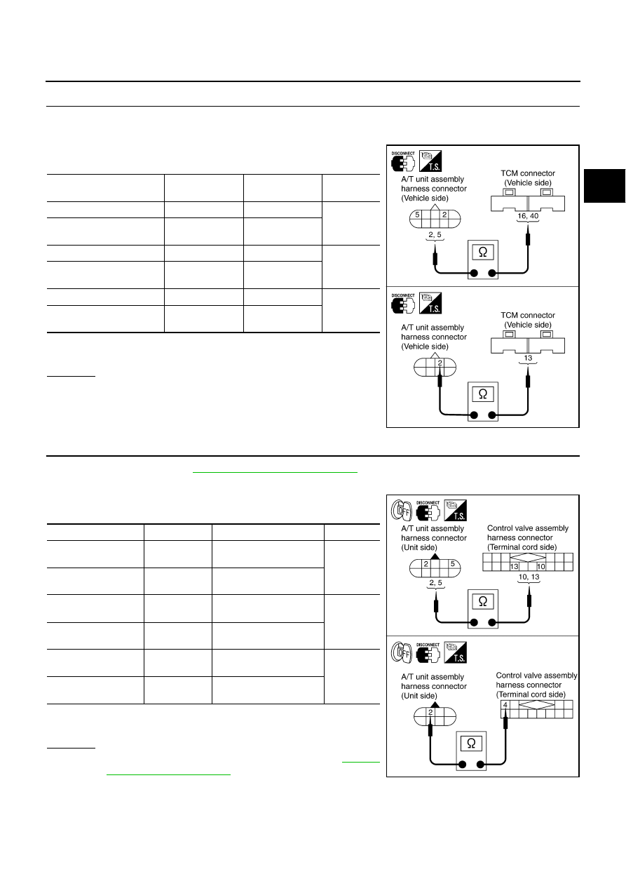
CHECK HARNESS BETWEEN TCM AND A/T UNIT ASSEMBLY HARNESS CONNECTOR

1.

Turn ignition switch OFF.

2.

Disconnect TCM connector.

3.

Check continuity between A/T unit assembly harness connector
and TCM connector.

4.

If OK, check harness for short to ground and short to power.

5.

Reinstall any part removed.

OK or NG

OK

>> GO TO 3.

NG

>> Repair open circuit or short to ground or short to power

in harness or connectors.

3. 

CHECK TERMINAL CORD ASSEMBLY

1.

Remove oil pan. Refer to 

AT-312, "Control Valve Assembly"

 .

2.

Disconnect A/T unit assembly harness connector and control valve assembly harness connector.

3.

Check continuity between A/T unit assembly harness connector
and control valve assembly harness connector.

4.

If OK, check harness for short to ground and short to power.

5.

Reinstall any part removed.

OK or NG

OK

>> Replace the control valve assembly. Refer to 

AT-312,

"Control Valve Assembly"

 .

NG

>> Repair open circuit or short to ground or short to power

in harness or connectors.

Item

Connector No.

Terminal No. 

(Wire color)

Continuity

TCM

F103

16 (W/G)

Yes

A/T unit assembly harness 
connector

F26

5 (W/G)

TCM

F104

40 (Y/G)

Yes

A/T unit assembly harness 
connector

F26

2 (Y/G)

TCM

F103

13 (W/L)

Yes

A/T unit assembly harness 
connector

F27

2 (W/L)

SCIA3095E

Item

Connector No.

Terminal No. (Wire color)

Continuity

A/T unit assembly 
harness connector

F26

2 (R)

Yes

Control valve assem-
bly harness connector

F302

10 (R)

A/T unit assembly 
harness connector

F26

5 (L)

Yes

Control valve assem-
bly harness connector

F302

13 (L)

A/T unit assembly 
harness connector

F27

2 (B/R)

Yes

Control valve assem-
bly harness connector

F301

4 (B/R)

SCIA3107E

AT-178

DTC P1731 A/T 1ST ENGINE BRAKING

4. 

CHECK DTC

Perform “DTC Confirmation Procedure”. Refer to 

AT-174, "DTC Confirmation Procedure"

 .

OK or NG

OK

>> INSPECTION END

NG

>> GO TO 5.

5. 

CHECK TCM

1.

Check TCM input/output signal. Refer to 

AT-86, "TCM Input/Output Signal Reference Values"

 .

2.

If NG, recheck TCM pin terminals for damage or loose connection with harness connector.

OK or NG

OK

>> INSPECTION END

NG

>> Repair or replace damaged parts.

DTC P1752 INPUT CLUTCH SOLENOID VALVE

AT-179

D

E

F

G

H

I

J

K

L

M

A

B

AT

DTC P1752 INPUT CLUTCH SOLENOID VALVE

PFP:31940

Description

ACS0048Q

Input clutch solenoid valve is controlled by the TCM in response to signals sent from the PNP switch, vehicle
speed sensor and accelerator pedal position sensor (throttle position sensor). Gears will then be shifted to the
optimum position.

CONSULT-II Reference Value

ACS004PH

On Board Diagnosis Logic

ACS0048R

This is an OBD-II self-diagnostic item.

Diagnostic trouble code “I/C SOLENOID/CIRC” with CONSULT-II or P1752 without CONSULT-II is
detected under the following conditions.

When TCM detects an improper voltage drop when it tries to operate the solenoid valve.

When TCM detects as irregular by comparing target value with monitor value.

Possible Cause

ACS0048S

Harness or connectors
(The solenoid circuit is open or shorted.)

Input clutch solenoid valve 

DTC Confirmation Procedure

ACS0048T

CAUTION:

Always drive vehicle at a safe speed.
NOTE:
If “DTC Confirmation Procedure” has been previously conducted, always turn ignition switch OFF and
wait at least 10 seconds before conducting the next test.
After the repair, perform the following procedure to confirm the malfunction is eliminated.

 WITH CONSULT-II

1.

Turn ignition switch ON. (Do not start engine.)

2.

Select “DATA MONITOR” mode for “A/T” with CONSULT-II.

3.

Start engine.

4.

Maintain the following conditions for at least 5 consecutive sec-
onds.
ACCELE POS: 1.5/8 - 2.0/8
Selector lever: “D” position 
Gear position: 3rd 

Þ

 4th Gear (I/C ON/OFF)   

5.

If DTC is detected go to “

AT-181, "Diagnostic Procedure"

 .

 WITH GST

Follow the procedure “With CONSULT-II”.

Item name

Condition 

Display value (Approx.)

I/C SOLENOID

Input clutch solenoid valve operates. 

0.6 - 0.8 A

Other conditions

0 - 0.05 A

SAT014K

AT-180

DTC P1752 INPUT CLUTCH SOLENOID VALVE

Wiring Diagram — AT — I/C

ACS0048U

TCWA0125E


Content   ..  71  72  73  74   ..