Infiniti M35/M45 Y50. Manual - part 680
 

  Index      Infiniti     Infiniti M35/M45 Y50 - service repair manual 2007 year


Search            copyright infringement  


Content   ..  678  679  680  681   ..


Infiniti M35/M45 Y50. Manual - part 680


DTC P0643 SENSOR POWER SUPPLY

EC-1193

[VK45DE]

C

D

E

F

G

H

I

J

K

L

M

A

EC

DTC P0643 SENSOR POWER SUPPLY

PFP:18919

On Board Diagnosis Logic

NBS005JY

This self-diagnosis has the one trip detection logic.

FAIL-SAFE MODE

When the malfunction is detected, ECM enters fail-safe mode and the MIL lights up. 

DTC Confirmation Procedure

NBS005JZ

NOTE:
If DTC Confirmation Procedure has been previously conducted, always turn ignition switch OFF and wait at
least 10 seconds before conducting the next test.
TESTING CONDITION:
Before performing the following procedure, confirm that battery voltage is more than 10V at idle.

 WITH CONSULT-II

1.

Turn ignition switch ON.

2.

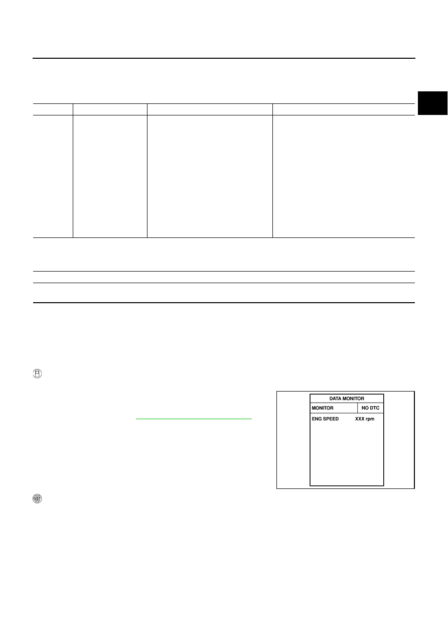
Select “DATA MONITOR” mode with CONSULT-II.

3.

Start engine and let it idle for 1 second.

4.

If DTC is detected, go to 

EC-1196, "Diagnostic Procedure"

 .

 WITH GST

Follow the procedure “WITH CONSULT-II” above.

DTC No.

Trouble diagnosis name

DTC detecting condition

Possible cause

P0643
0643

Sensor power supply 
circuit short

ECM detects a voltage of power source 
for sensor is excessively low or high.

●

Harness or connectors
(APP sensor 1 circuit is shorted.)
(EVAP control system pressure sensor is 
shorted.)
(Refrigerant pressure sensor circuit is 
shorted.)
(PSP sensor circuit is shorted.)
(Battery current sensor circuit is shorted.)

●

Accelerator pedal position sensor

●

EVAP control system pressure sensor

●

Refrigerant pressure sensor

●

Power steering pressure sensor

●

Battery current sensor

Engine operation condition in fail-safe mode

ECM stops the electric throttle control actuator control, throttle valve is maintained at a fixed opening (approx. 5 degrees) by the return 
spring.

SEF058Y

EC-1194

[VK45DE]

DTC P0643 SENSOR POWER SUPPLY

Wiring Diagram

NBS005K0

TBWT1496E

DTC P0643 SENSOR POWER SUPPLY

EC-1195

[VK45DE]

C

D

E

F

G

H

I

J

K

L

M

A

EC

Specification data are reference values and are measured between each terminal and ground.

CAUTION:

Do not use ECM ground terminals when measuring input/output voltage. Doing so may result in dam-
age to the ECM's transistor. Use a ground other than ECM terminals, such as the ground.

TER-

MINAL 

NO.

WIRE 

COLOR

ITEM

CONDITION

DATA (DC Voltage)

48

BR

Sensor power supply
(EVAP control system pres-
sure sensor)

[Ignition switch: ON]

Approximately 5V

49

B/Y

Sensor power supply
(Refrigerant pressure sen-
sor, Battery current sensor)

[Ignition switch: ON]

Approximately 5V

68

L/Y

Sensor power supply
(Power steering pressure 
sensor)

[Ignition switch: ON]

Approximately 5V

82

W

Sensor ground
(APP sensor 1)

[Engine is running]

●

Warm-up condition

●

Idle speed

Approximately 0V

83

P

Sensor ground
(APP sensor 2)

[Engine is running]

●

Warm-up condition

●

Idle speed

Approximately 0V

90

L

Sensor power supply
(APP sensor 1)

[Ignition switch: ON]

Approximately 5V

91

BR

Sensor power supply
(APP sensor 2)

[Ignition switch: ON]

Approximately 5V

98

R

Accelerator pedal position 
sensor 2

[Ignition switch: ON]

●

Engine stopped

●

Accelerator pedal: Fully released

0.20 - 0.55V

[Ignition switch: ON]

●

Engine: Stopped

●

Accelerator pedal: Fully depressed

1.85 - 2.40V

106

LG

Accelerator pedal position 
sensor 1

[Ignition switch: ON]

●

Engine: Stopped

●

Accelerator pedal: Fully released

0.4 - 1.1V

[Ignition switch: ON]

●

Engine: Stopped

●

Accelerator pedal: Fully depressed

3.7 - 4.8V

EC-1196

[VK45DE]

DTC P0643 SENSOR POWER SUPPLY

Diagnostic Procedure

NBS005K1

1. 

CHECK GROUND CONNECTIONS

1.

Turn ignition switch OFF.

2.

Loosen and retighten ground screws on the body. 
Refer to 

EC-864, "Ground Inspection"

 .

OK or NG

OK

>> GO TO 2.

NG

>> Repair or replace ground connections.

2. 

CHECK ACCELERATOR PEDAL POSITION SENSOR 1 POWER SUPPLY CIRCUIT

1.

Disconnect accelerator pedal position (APP) sensor (1) harness
connector.

2.

Turn ignition switch ON.

3.

Check voltage between APP sensor terminal 4 and ground with
CONSULT-II or tester.

OK or NG

OK

>> GO TO 5.

NG

>> GO TO 3.

1.

Body ground M70

2.

Body ground M16

PBIB2782E

PBIB2704E

Voltage: Approximately 5V

PBIA9606J


Content   ..  678  679  680  681   ..