Infiniti M35/M45 Y50. Manual - part 251
 

  Index      Infiniti     Infiniti M35/M45 Y50 - service repair manual 2007 year


Search            copyright infringement  


Content   ..  249  250  251  252   ..


Infiniti M35/M45 Y50. Manual - part 251


INTELLIGENT KEY SYSTEM

BL-73

C

D

E

F

G

H

J

K

L

M

A

B

BL

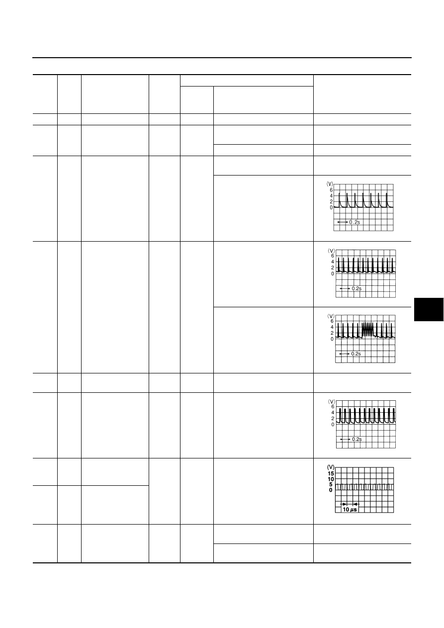
Terminals and Reference Value for Intelligent Key Unit

NIS001XD

Termi-

nal

Wire 

Color

Item

Signal 

Input/

Output

Condition

Voltage (V)

Approx.

Ignition 

Switch 

Position

Operation or Conditions

1

SB

Power source (Fuse)

Input

—

—

Battery voltage

2

GR

Door request switch 
(driver side)

Input

—

Press door request switch (driver 
side).

0

Other than above

5

4

B/Y

Remote keyless entry 
receiver RSSI signal

Input/

Output

LOCK

When Intelligent Key is in vehicle, 
press push-button ignition switch

0

Other than above

5

B/W

Remote keyless entry 
receiver signal

Input/

Output

LOCK

Waiting state

Any operation using Intelligent 
Key

6

B

Remote keyless entry 
receiver ground

—

—

—

0

7

B/R

Remote keyless entry 
receiver power supply

Output

LOCK

—

11

LG

Outside key antenna 
(+) signal
(passenger side)

Output

LOCK

Press door request switch (pas-
senger side).

12

G

Outside key antenna 
(-) signal
(passenger side)

13

LG/B

Key slot illumination 
signal

Output

LOCK

Insert Intelligent Key into key slot 
and driver side door is open.

Illuminate: Battery voltage

Does not illuminate: 0

Remove Intelligent Key from key 
slot.

0

PIIB5657J

OCC3879D

OCC3880D

OCC3881D

SIIA1910J

BL-74

INTELLIGENT KEY SYSTEM

17

O/B

Outside key antenna 
(+) signal
 (Trunk room)

Output

LOCK

Press trunk opener request 
switch.

18

L

Outside key antenna 
(-) signal 
(Trunk room)

19

BR/Y

Key switch signal

Input

LOCK

Insert Intelligent Key into key slot.

0

Remove Intelligent Key from key 
slot.

Battery voltage

20

B

Ground

—

ON

—

0

22

O

Door request switch 
(passenger side)

Input

—

Press door request switch
(passenger side).

0

Other than above

5

23

B

Trunk lid opener can-
cel switch

Input

—

Trunk lid opener cancel switch is 
ON

0

Trunk lid opener cancel switch is 
OFF (cancel)

5

24

O/L

Outside key antenna 
(+) signal (driver side)

Output

LOCK

Press door request switch (driver 
side).

25

Y

Outside key antenna 
(-) signal (driver side)

26

BR/W

Unlock sensor
(driver side)

Input

—

Door (driver side) is locked.

Battery voltage

Door (driver side) is unlocked.

0

27

V

P range switch

Input

—

Selector lever is in “P” position.

0

Other than above

Battery voltage

30

L/W

Ignition switch (ACC)

Input

ACC

—

Battery voltage

31

GR

Ignition switch (ON)

Input

ON

—

Battery voltage

35

LG

Vehicle speed signal

Input

ON

At speedometer operation (vehi-
cle speed approx. 40 km/h)

37

P

CAN-L

Input/

Output

—

—

—

38

L

CAN-H

Input/

Output

—

—

—

39

BR/W

Push-button ignition 
switch signal

Input

—

Press push-button ignition switch

0

Other than above

Battery voltage

40

B

Ground

—

ON

—

0

41

Y

Power source (Fuse)

Input

—

—

Battery voltage

Termi-

nal

Wire 

Color

Item

Signal 

Input/

Output

Condition

Voltage (V)

Approx.

Ignition 

Switch 

Position

Operation or Conditions

SIIA1910J

SIIA1910J

PKIA1935E

INTELLIGENT KEY SYSTEM

BL-75

C

D

E

F

G

H

J

K

L

M

A

B

BL

47

LG

Inside key antenna 
(+) signal
(Instrument center)

Output

LOCK

Any door open 

→

 all door close

48

V

Inside key antenna (-) 
signal
(Instrument center)

49

B

Inside key antenna 
(+) signal
(Console)

Output

LOCK

Any door open 

→

 all door close

50

W

Inside key antenna (-) 
signal
(Console)

51

R/L

Inside key antenna 
(+) signal
(Rear seat)

Output

LOCK

Any door open 

→

 all door closed

52

R/W

Inside key antenna (-) 
signal
(Rear seat)

53

G/W

Inside key antenna 
(+) signal
(Trunk room)

Output

LOCK

Any door open 

→

 all door close

54

LG

Inside key antenna 
(-) signal
(Trunk room)

55

P

Intelligent Key warn-
ing buzzer

Output

LOCK

Operate door 

request switch.

Buzzer 
OFF

Battery voltage

Sound 
buzzer

0

56

B

Ground

—

ON

—

0

57

L

Power source (Fuse)

Input

—

—

Battery voltage

58

O

A/T device power 
supply 

Output

LOCK

Wake-up state (Open drive side 
door)

Battery voltage

Sleep state (After 30 seconds or 
more since all doors are closed 
under the condition that the igni-
tion switch is in the LOCK posi-
tion)

0

61

GR/R

Trunk opener request 
switch

Input

—

Press trunk opener request 
switch.

0

Other than above

5

72

B

Ground

—

ON

0

Termi-

nal

Wire 

Color

Item

Signal 

Input/

Output

Condition

Voltage (V)

Approx.

Ignition 

Switch 

Position

Operation or Conditions

SIIA1910J

SIIA1910J

SIIA1910J

SIIA1910J

BL-76

INTELLIGENT KEY SYSTEM

Terminals and Reference Value for BCM

NIS001XE

*1: In the state that hazard reminder operates.
*2: In the state that room lamp switch is in “DOOR” position.

Terminals and Reference Value for IPDM E/R

NIS001XF

Termi-

nal

Wire 

Color

Item

Signal 

Input/

Output

Condition

Voltage (V)

Approx.

11

V

Ignition switch (ACC)

Input

Ignition switch is in ACC or ON position

Battery voltage

12

P

Front door switch passenger 
side

Input

Door open (ON) 

→

 Close (OFF)

0 

→

 8

13

O/L

Rear door switch RH

Input

Door open (ON) 

→

 Close (OFF)

0 

→

 Battery voltage

37

LG

Key switch signal

Input

Insert Intelligent Key into key slot.

Battery voltage

Remove Intelligent Key from key slot.

0

38

W

Ignition switch (ON)

Input

Ignition switch is in ON or START posi-
tion.

Battery voltage

39

L

CAN-H

Input/

Output

—

—

40

P

CAN-L

Input/

Output

—

—

42

P

Power supply (fuse)

Input

—

Battery voltage

52

B

Ground

—

—

0

55

W

Power supply (Fusible link)

Input

—

Battery voltage

57

SB

Trunk room lamp switch

Input

Trunk lid open (ON) 

→

 Close (OFF)

0 

→

 Battery voltage

62

V

Front door switch driver side

Input

Door open (ON) 

→

 Close (OFF)

0 

→

 Battery voltage

63

R/G

Rear door switch LH

Input

Door open (ON) 

→

 Close (OFF)

0 

→

 Battery voltage

Terminal 

Wire 

Color

Item

Signal 

Input/

Output

Condition

Voltage (V)

Approx.

48

G/B

Horn relay

Output

Press panic alarm bottom.

Horn sounds.

0

Horn does not sound.

Battery voltage

49

L

CAN-H

Input/

Output

—

—

50

P

CAN-L

Input/

Output

—

—


Content   ..  249  250  251  252   ..