Infiniti M35/M45 Y50. Manual - part 181
 

  Index      Infiniti     Infiniti M35/M45 Y50 - service repair manual 2007 year


Search            copyright infringement  


Content   ..  179  180  181  182   ..


Infiniti M35/M45 Y50. Manual - part 181


DIAGNOSIS SYSTEM

AV-101

[WITHOUT MOBILE ENTERTAINMENT SYSTEM]

C

D

E

F

G

H

I

J

L

M

A

B

AV

Rear View Monitor Guiding Line Adjustment

NKS0048Y

1.

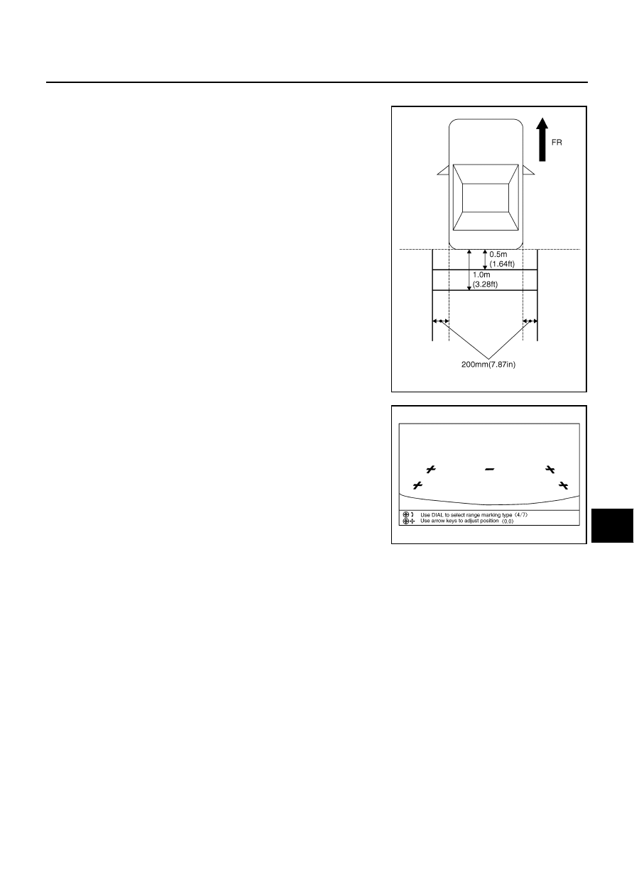
Draw lines on rearward area of the vehicle passing through the
following points: 20 cm (7.87 in) from both sides of the vehicle,
and 0.5 m (1.64 ft), 1.0 m (3.28 ft) from the rear end of the
bumper.

2.

Set into “Adjust offset of rear view camera” mode of Confirma-
tion/Adjustment mode.

3.

Rotate the center dial, and then select the guiding line pattern so
that its angle is aligned with the correction line of the rear of the
vehicle.

4.

Make fine adjustment to the correction line of the rear of the vehicle with up/down/left/right switches so
that its position is aligned with the guiding line. Press “OK” switch and record the adjusted guiding line
position to the camera control unit.

CAUTION:

Never operate other function such as pressing BACK while writing index data.
If Confirmation/Adjustment mode does not function in the above procedure, perform one of the
following service to adjust the index again. 

●

Remove battery for five min. Then reconnect battery.

●

Remove camera control unit connector for five min. Then reconnect camera control unit con-
nector.

SKIB3691E

Selected pattern

: 7

SKIB3689E

Up/Down adjustment range

: –20 - 20

Left/Right adjustment range

: –20 - 20

AV-102

[WITHOUT MOBILE ENTERTAINMENT SYSTEM]

DIAGNOSIS SYSTEM

CONSULT-II Functions (Multi AV)

NKS0048Z

CONSULT-II can display each diagnostic item using the diagnostic test modes shown following.

OPERATION PROCEDURE

CAUTION:

If CONSULT-II is used with no connection of CONSULT-II CONVERTER, malfunctions might be
detected in self-diagnosis depending on control unit which carry out CAN communication.

1.

Turn ignition switch OFF.

2.

Connect CONSULT-II and CONSULT-II CONVERTER to data
link connector, and turn ignition switch ON.

3.

Touch “START (NISSAN BASED VHCL)”.

4.

Touch “MULTI AV”
If “MULTI AV” is not indicated, check the following item.

●

AV (NAVI) control unit power supply and ground circuit.

●

CONSULT-II data link connector (DLC) circuit
Refer to 

LAN-42, "Precautions When Using CONSULT-II"

 .

Diagnosis mode

Description

SELF-DIAG RESULTS

●

Performs the connection diagnosis of communication circuit between AV (NAVI) control unit and 
system and displays the current and past malfunctions collectively.

●

The DVD-ROM drive diagnosis of NAVI control unit and the connection diagnosis between NAVI 
control unit and GPS antenna can be performed (DVD-ROM drive will not be diagnosed when 
no map DVD-ROM is in it)

DATA MONITOR

The diagnosis of vehicle signal that is input to the AV (NAVI) control unit can be performed

CAN DIAG SUPPORT MNTR

The transmitting/receiving of CAN communication can be monitored. Refer to 

LAN-44, "CAN Diag-

nostic Support Monitor"

 .

AV COMM MONITOR

The transmitting/receiving of a system can be monitored

ECU PART NUMBER

The part number of AV (NAVI) control unit can be checked

SHIA0179E

BCIA0029E

BCIA0030E

DIAGNOSIS SYSTEM

AV-103

[WITHOUT MOBILE ENTERTAINMENT SYSTEM]

C

D

E

F

G

H

I

J

L

M

A

B

AV

5.

Select diagnosis item on “SELECT DIAG MODE” screen.

SELF-DIAG RESULTS

The self-diagnosis is started and self-diagnostic results are dis-
played by touching “START” after selecting “SELF-DIAG RESULTS”.

●

In CONSULT-II self-diagnosis, self-diagnostic results and error
history are displayed collectively.

●

The current malfunction indicates “CRNT”. The past malfunction
indicates “PAST”.

●

If DTC [U1000], [U1300] are detected, “0” is displayed at “TIME”.
If it is normal the next time ignition switch is ON of next time, add
1 to the “TIME”.

Display Item of SELF-DIAG RESULTS

Self-diagnostic results may be displayed simultaneously according to the cause. If some error items are dis-
played simultaneously, the detection of the cause can be performed by the combination of display items

BCIA0031E

SKIB3674E

Error item

Description

Possible cause/Action to take

CAN COMM CIRCUIT [U1000]

CAN communication malfunction is 
detected

Print out the self-diagnostic results and go to 

LAN-42, "Precautions When Using CONSULT-
II"

 .

CONTROL UNIT (CAN) [U1010]

CAN initial diagnosis malfunction is 
detected

Replace AV (NAVI) control unit
Refer to 

AV-131, "AV (NAVI) Control Unit"

 .

CONTROL UNIT (AV) [U1310]

AV communication circuit initial diagno-
sis malfunction is detected

Replace AV (NAVI) control unit
Refer to 

AV-131, "AV (NAVI) Control Unit"

 .

●

AV COMM CIRCUIT [U1300]

●

SWITCH CONN [U1240]

●

DVD DECK CONN [U1248]

●

AUDIO H/U CONN [U1249]

●

AMP CONN [U124E]

●

REAR CAMERA CONN [U1252]

Malfunction is detected on communi-
cation circuit between AV (NAVI) con-
trol unit and DVD player

●

Communication circuit between AV (NAVI) 
control unit and DVD player

●

AV (NAVI) control unit

●

DVD player

●

AV COMM CIRCUIT [U1300]

●

SWITCH CONN [U1240]

●

AUDIO H/U CONN [U1249]

●

AMP CONN [U124E]

●

REAR CAMERA CONN [U1252]

BOSE surround 5.1ch system

●

Malfunction is detected on communi-
cation circuit between DVD player 
and multifunction switch

●

Communication circuit between DVD player 
and multifunction switch

●

DVD player

●

Multifunction switch

BOSE 2ch system

●

Malfunction is detected on communi-
cation circuit between AV (NAVI) 
control unit and multifunction switch

●

Communication circuit between AV (NAVI) 
control unit and multifunction switch

●

AV (NAVI) control unit

●

Multifunction switch

●

AV COMM CIRCUIT [U1300]

●

AUDIO H/U CONN [U1249]

●

AMP CONN [U124E]

●

REAR CAMERA CONN [U1252]

Malfunction is detected on communi-
cation circuit between multifunction 
switch and camera control unit

●

Communication circuit between multifunction 
switch and camera control unit

●

Multifunction switch

●

Camera control unit

AV-104

[WITHOUT MOBILE ENTERTAINMENT SYSTEM]

DIAGNOSIS SYSTEM

●

AV COMM CIRCUIT [U1300]

●

AUDIO H/U CONN [U1249]

●

AMP CONN [U124E]

Base system

●

Audio unit power supply and ground 
circuit malfunction is detected

●

Malfunction is detected on communi-
cation circuit between multifunction 
switch and audio unit

●

Malfunction is detected on communi-
cation signal between audio unit and 
AV (NAVI) control unit

●

Audio unit power supply and ground circuit

●

Communication circuit between multifunction 
switch and audio unit

●

Multifunction switch

●

Audio unit

●

AV (NAVI) control unit

BOSE system

●

Malfunction is detected on communi-
cation circuit between camera con-
trol unit and BOSE amp

●

Communication circuit between camera con-
trol unit and BOSE amp

●

Camera control unit

●

BOSE amp

●

AV COMM CIRCUIT [U1300]

●

AUDIO H/U CONN [U1249]

●

Audio unit power supply and ground 
circuit malfunction is detected

●

Malfunction is detected on communi-
cation circuit between BOSE amp 
and audio unit

●

Malfunction is detected on communi-
cation signal between audio unit and 
AV (NAVI) control unit

●

Audio unit power supply and ground circuit

●

Communication circuit between BOSE amp 
and audio unit

●

Audio unit

●

AV (NAVI) control unit

●

BOSE amp

●

AV COMM CIRCUIT [U1300]

●

REAR CAMERA CONN [U1252]

●

Camera control unit power supply 
and ground circuit malfunction is 
detected

●

Malfunction is detected on communi-
cation signal between camera con-
trol unit and AV (NAVI) control unit

●

Camera control unit power supply and ground 
circuit

●

Camera control unit

●

AV (NAVI) control unit

●

AV COMM CIRCUIT [U1300]

●

SWITCH CONN [U1240]

●

Multifunction switch power supply 
and ground circuit malfunction is 
detected

●

Malfunction is detected on communi-
cation signal between multifunction 
switch and AV (NAVI) control unit

●

Multifunction switch power supply and ground 
circuit

●

Multifunction switch 

●

AV (NAVI) control unit

●

AV COMM CIRCUIT [U1300]

●

DVD DECK CONN [U1248]

●

DVD player power supply and 
ground circuit malfunction detected

●

Malfunction is detected on communi-
cation signal between DVD player 
and AV (NAVI) control unit

●

DVD player power supply and ground circuit

●

DVD player

●

AV (NAVI) control unit

●

AV COMM CIRCUIT [U1300]

●

AMP CONN [U124E]

●

BOSE amp power supply and 
ground circuit malfunction is 
detected

●

Malfunction is detected on communi-
cation signal between BOSE amp 
and AV (NAVI) control unit

●

BOSE amp power supply and ground circuit

●

BOSE amp

●

AV (NAVI) control unit

FRONT DISP CONN [U1243]

●

Front display unit power supply and 
ground circuit malfunction is 
detected

●

Malfunction is detected on communi-
cation circuit between front display 
unit and AV (NAVI) control unit

●

Malfunction is detected on communi-
cation signal between front display 
unit and AV (NAVI) control unit

●

Front display unit power supply and ground

●

Communication circuit between front display 
unit and AV (NAVI) control unit

●

Front display unit

●

AV (NAVI) control unit

Error item

Description

Possible cause/Action to take


Content   ..  179  180  181  182   ..