Infiniti M35/M45 Y50. Manual - part 1128


  Index      Infiniti     Infiniti M35/M45 Y50 - service repair manual 2007 year


Search            copyright infringement  


Content   ..  1126  1127  1128  1129   ..


Infiniti M35/M45 Y50. Manual - part 1128


TROUBLE DIAGNOSIS

TF-19

C

E

F

G

H

I

J

K

L

M

A

B

TF

TDWT0023E

TF-20

TROUBLE DIAGNOSIS

Trouble Diagnosis Chart for Symptoms

NDS000DK

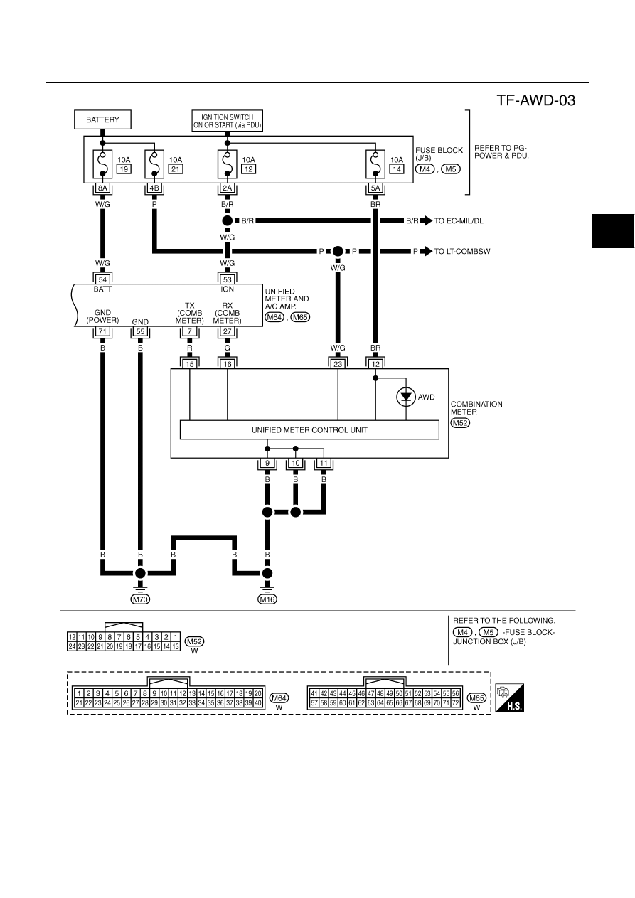
If AWD warning lamp turns ON, perform self-diagnosis. Refer to 

TF-22, "SELF-DIAG RESULT MODE"

 .

NOTE:
Light tight-corner braking symptom may occur depending on driving conditions. This is not malfunction.

AWD Control Unit Input/Output Signal Reference Values

NDS000DL

AWD CONTROL UNIT INSPECTION TABLE
Specifications with CONSULT-II

Symptom

Condition

Check item

Reference page

AWD warning lamp does not turn ON when 
the ignition switch is turned to ON.
(AWD warning lamp check)

Ignition switch: ON

CAN communication line

TF-33

Unified meter and A/C amp.

Unified meter control unit

AWD warning lamp does not turn OFF sev-
eral seconds after engine started.

Engine running

CAN communication line

TF-33

Power supply and ground for AWD con-
trol unit

Unified meter and A/C amp.

Unified meter control unit

AWD solenoid

AWD actuator relay (integrated in AWD 
control unit)

Wheel sensor

Heavy tight-corner braking symptom occurs 
when the vehicle is driven and the steering 
wheel is turned fully to either side after the 
engine is started. (See NOTE.)

●

While driving

●

Steering wheel is 
turned fully to either 
sides

CAN communication line

TF-35

Accelerator pedal position signal

AWD solenoid

Mechanical malfunction of electric con-
trolled coupling (clutch sticking etc.)

Vehicle does not enter AWD mode even 
though AWD warning lamp turned to OFF.

While driving

CAN communication line


TF-36

AWD solenoid

Mechanical malfunction of electric con-
trolled coupling (Mechanical engage-
ment of clutch is not possible.)

While driving, AWD warning lamp flashes 
rapidly. (When flashing in approx. 1 minute 
and then turning OFF.)
Rapid flashing: 2 times/second

While driving

Protection function is activated due to 
heavy load to electric controlled cou-
pling. (AWD system is not malfunction-
ing. Also, optional distribution of torque 
sometimes becomes rigid before lamp 
flashes rapidly, but it is not malfunction.)

TF-37

While driving, AWD warning lamp flashes 
slowly. (When continuing to flash until turn-
ing ignition switch OFF)
Slow flashing: 1 time/2 seconds

●

While driving

●

Vehicle speed: 20 km/h 
(12 MPH) or more

Tire size is different between front and 
rear of vehicle.

TF-37

Monitor item [Unit]

Content

Condition

Display value

FR RH SENSOR [km/h] or [mph]

Wheel speed (Front wheel 
right)

Vehicle stopped

0.00 km/h (0.00 mph)

Vehicle running

CAUTION:

Check air pressure of tire under 
standard condition.

Approximately equal to 
the indication on speed-
ometer (Inside of 

±

10%)

FR LH SENSOR [km/h] or [mph]

Wheel speed (Front wheel 
left)

Vehicle stopped

0.00 km/h (0.00 mph)

Vehicle running

CAUTION:

Check air pressure of tire under 
standard condition.

Approximately equal to 
the indication on speed-
ometer (Inside of 

±

10%)

TROUBLE DIAGNOSIS

TF-21

C

E

F

G

H

I

J

K

L

M

A

B

TF

*

1

 : The values are changed by throttle opening and engine speed.

*

2

 : Mode switch is not equipped, but displayed.

CONSULT-II Function (ALL MODE AWD/4WD)

NDS000DM

FUNCTION

CONSULT-II can display each diagnostic item using the diagnostic test modes shown following.

RR RH SENSOR [km/h] or [mph]

Wheel speed (Rear wheel 
right)

Vehicle stopped

0.00 km/h (0.00 mph)

Vehicle running

CAUTION:

Check air pressure of tire under 
standard condition.

Approximately equal to 
the indication on speed-
ometer (Inside of 

±

10%)

RR LH SENSOR [km/h] or [mph]

Wheel speed (Rear wheel 
left)

Vehicle stopped

0.00 km/h (0.00 mph)

Vehicle running

CAUTION:

Check air pressure of tire under 
standard condition.

Approximately equal to 
the indication on speed-
ometer (Inside of 

±

10%)

BATTERY VOLT [V]

Power supply voltage for 
AWD control unit

Ignition switch: ON

Battery voltage

THRTL POS SEN [%]

Throttle opening condition

When depressing accelerator pedal
(Value rises gradually in response to 
throttle position.)

0 - 100%

ETS SOLENOID [A]

Monitored value of current at 
AWD solenoid

Engine running

●

At idle speed

Approx. 0.000A

Engine running

●

When depressing accelerator 
pedal

Approx. 0.000 - 0.500A*

1

STOP LAMP SW [ON/OFF]

Condition of brake pedal 
operation

Brake pedal: Depressed

ON

Brake pedal: Released

OFF

ENG SPEED SIG [RUN/STOP]

Condition of engine running

Engine stopped
(Engine speed: Less than 400 rpm)

STOP

Engine running
(Engine speed: 400 rpm or more)

RUN

ETS ACTUATOR [ON/OFF]

Operating condition of AWD 
actuator relay (integrated in 
AWD control unit)

Engine stopped (Ignition 
switch: ON)

OFF

Engine running

ON

4WD WARN LAMP [ON/OFF]

AWD warning lamp condition

AWD warning lamp: ON

ON

AWD warning lamp: OFF

OFF

4WD MODE SW*

2 

 [AUTO]

Input condition from mode 
switch

Always

AUTO

4WD MODE MON [AUTO]

Control status of AWD

Engine running

AUTO

DIS-TIRE MONI [mm]

Improper size tire installed 
condition

Vehicle running with normal size tire 
installed

0-4 mm

Vehicle running with improper size 
tire installed (Front/rear tire size dif-
ference, wear condition)

4-8 mm, 8- mm

P BRAKE SW [ON/OFF]

Condition of parking brake

Parking brake operated

ON

Parking brake not operated

OFF

Monitor item [Unit]

Content

Condition

Display value

Diagnostic test mode

Function

Reference 

page

Self-diagnostic results

●

Self-diagnostic results can be read and erased quickly.

TF-22

Data monitor

●

Input/Output data in the AWD control unit can be read.

TF-24

TF-22

TROUBLE DIAGNOSIS

CONSULT-II SETTING PROCEDURE

Refer to 

GI-38, "CONSULT-II Start Procedure"

 .

SELF-DIAG RESULT MODE
Operation Procedure

1.

Perform “CONSULT-II Start Procedure”. Refer to 

GI-38, "CONSULT-II Start Procedure"

 .

2.

Start engine and drive at 30 km/h (19 MPH) or more for approx. 1 minute.

3.

Stop vehicle. With engine at idle, touch “SELF-DIAG RESULTS”.
Display shows malfunction experienced since the last erasing
operation.

NOTE:

●

The details for “TIME” are as follow:

–

“0”: Error currently detected with AWD control unit.

–

Except for “0”: Error detected in the past and memorized
with AWD control unit.
Detects frequency of driving after DTC occurs (frequency
of turning ignition switch “ON/OFF”).

Display Item List

CAUTION:

●

If “CAN COMM CIRCUIT [U1000]” is displayed with other DTCs, first perform the trouble diagnosis for CAN communica-
tion line.

●

Make sure that ABS warning lamp turns OFF by driving for a minute at vehicle speed of 30 km/h (19 MPH) or more after
turning ignition switch “OFF” if AWD warning lamp turns ON with system malfunction of “ABS SYSTEM [C1203]”. AWD
warning lamp may not turn OFF if it is normal unless ignition switch turns OFF at once and engine restarts after that.

How to Erase Self-Diagnostic Results

1.

Perform applicably inspection of malfunctioning item and then repair or replace.

2.

Start engine and drive at 30 km/h (19 MPH) or more for approx. 1 minute.

3.

Make sure that ABS warning lamp turns OFF.

CAN diagnostic support monitor

●

The results of transmit/receive diagnosis of CAN communication can be read.

LAN-44

Active test

●

Diagnostic Test Mode in which CONSULT-II drives some actuators apart from 
the AWD control unit and also shifts some parameters in a specified range.

TF-25

ECU part number

●

AWD control unit part number can be read.

TF-25

Diagnostic test mode

Function

Reference 

page

SDIA2217E

Items (CONSULT-II screen 

terms)

Diagnostic item is detected when...

Check item

CONTROLLER FAILURE
[C1201]

Malfunction has occurred inside AWD control unit.

TF-27, "AWD Control Unit"

ABS SYSTEM
[C1203]

Malfunction related to wheel sensor has been detected by ABS actu-
ator and electric unit (control unit).

TF-27, "ABS System"

4WD SOLENOID
[C1204]

Malfunction related to AWD solenoid has been detected.

TF-28, "AWD Solenoid"

4WD ACTUATOR RLY
[C1205]

Malfunction has been detected from AWD actuator relay integrated 
with AWD control unit, or malfunction related to AWD solenoid has 
been detected.

TF-31, "AWD Actuator 
Relay"

 or 

TF-28, "AWD 

Solenoid"

ENGINE SIGNAL 1
[C1210]

Malfunction has been detected from ECM.

TF-32, "Engine Control Sig-
nal"

CAN COMM CIRCUIT
[U1000]

When AWD control unit is not transmitting or receiving CAN commu-
nication signal for 2 seconds or more.

TF-32, "CAN Communica-
tion Line"

NO DTC IS DETECTED.
FURTHER TESTING MAY BE 
REQUIRED.

No NG item has been detected.

—


Content   ..  1126  1127  1128  1129   ..