Infiniti M35/M45 Y50. Manual - part 9


  Index      Infiniti     Infiniti M35/M45 Y50 - service repair manual 2007 year


Search            copyright infringement  


Content   ..  7  8  9  10   ..


Infiniti M35/M45 Y50. Manual - part 9


TROUBLE DIAGNOSIS - GENERAL DESCRIPTION

ACS-29

[ICC]

C

D

E

F

G

H

I

J

L

M

A

B

ACS

TROUBLE DIAGNOSIS - GENERAL DESCRIPTION

PFP:00000

Fail-Safe Function

NKS004CV

When a malfunction occurs in ICC system, a chime sounds a beep, the system is released and ICC system
warning lamp in combination meter illuminates. System setting is not accepted when malfunction is detected.
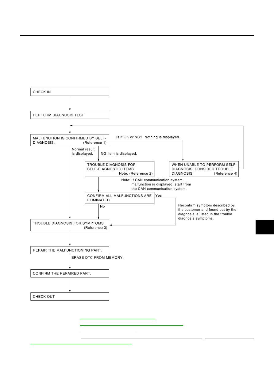
Work Flow

NKS004CW

Reference 1··· Refer to 

ACS-34, "Self-Diagnostic Function"

 .

Reference 2··· Refer to 

ACS-40, "Diagnostic Trouble Code (DTC) Chart"

 .

Reference 3··· Refer to 

ACS-62, "Symptom Chart"

 .

Reference 4··· Refer to 

GI-39, "CONSULT-II Data Link Connector (DLC) Circuit"

 /

ACS-36, "SELF-DIAG-

NOSIS BY DOT MATRIX LCD WILL NOT RUN"

 .

SKIA1227E

ACS-30

[ICC]

TROUBLE DIAGNOSIS - GENERAL DESCRIPTION

CONSULT-II Function (ICC)

NKS004CX

DESCRIPTION

CONSULT-II can display each diagnostic item using the diagnostic test modes shown following.

CONSULT-II BASIC OPERATION

Refer to 

GI-38, "CONSULT-II Start Procedure"

 .

WORK SUPPORT
Work Item

Cause of Auto-Cancel

1.

Touch “WORK SUPPORT” on the “SELECT DIAG MODE”
screen. 

2.

Touch “CAUSE OF AUTO-CANCEL” on the “SELECT WORK
ITEM” screen.

3.

Cause of automatic cancellation screen will be shown.

NOTE:

Last five cancel (system cancel) causes are displayed.

“CAUSE OF AUTO-CANCEL” displays times of ignition switch
ON/OFF up to 254 maximum. 254 is kept though the number
exceeds 254. The number returns to 0 when detecting the
same cancellation causes. 

Test mode

Function

Reference page

WORK SUPPORT

Monitors aiming direction to facilitate laser beam aiming operation.

Indicates causes of automatic cancellation of the ICC system.

ACS-30

SELF-DIAGNOSTIC RESULTS

Displays malfunctioning system memorized in ICC sensor integrated unit.

ACS-31

DATA MONITOR

Displays real-time input/output data of ICC sensor integrated unit.

ACS-31

CAN DIAG SUPPORT MNTR

The results of transmit/receive diagnosis of CAN communication can be read.

LAN-44

ACTIVE TEST

Enables operation check of electrical loads by sending driving signal to them.

ACS-33

ECU PART NUMBER

Displays part number of ICC sensor integrated unit.

Work item

Function

CAUSE OF AUTO-CANCEL

Indicates causes of automatic cancellation of the ICC system.

LASER BEAM ADJUST

Outputs laser beam, calculates dislocation of the beam, and indicates adjustment direction.

SKIA6191E

TROUBLE DIAGNOSIS - GENERAL DESCRIPTION

ACS-31

[ICC]

C

D

E

F

G

H

I

J

L

M

A

B

ACS

Display Item List

Laser Beam Adjust

For details, refer to 

ACS-15, "LASER BEAM AIMING ADJUSTMENT"

 .

SELF-DIAGNOSTIC RESULTS

For details, refer to 

ACS-40, "Diagnostic Trouble Code (DTC) Chart"

 .

DATA MONITOR
Operation Procedure

1.

Touch “DATA MONITOR” on “SELECT DIAG MODE” screen. 

2.

Touch any of “MAIN SIGNALS” and “SELECTION FROM
MENU” on selection screen.

3.

Touch “START”.

4.

Display the data monitor.

5.

Touch “COPY” to print data if necessary.

Monitored Item

×

: Applicable

Cause of cancellation

Description

OPERATING WIPER

Windshield wipers were operated at HI or LO speed operation. 

OPERATING ABS

ABS function was operated.

OPERATING TCS

TCS function was operated.

OPERATING VDC

VDC function was operated.

OPE SW VOLT CIRC

Outside the standard control switch input voltage was detected.

ECM CIRCUIT

ECM did not permit ICC operation.

LASER SUN BEAM

Intense light such as sunlight entered ICC sensor integrated unit light sensing part.

LASER TEMP

Temperature around ICC sensor integrated unit became low.

OP SW DOUBLE TOUCH

ICC steering switches were pressed at the same time.

WHL SPD ELEC NOISE

Wheel speed sensor signal caught electromagnetic noise.

VDC/TCS OFF SW

VDC OFF switch was pressed.

WHEEL SPD UNMATCH

Wheel speed became different from A/T vehicle speed.

TIRE SLIP

Wheel slipped.

IGN LOW VOLT

Power supply voltage became low.

SNOW MODE SW

Snow mode switch was pressed.

VHCL SPD DOWN

Vehicle speed becomes 20 MPH (32 km/h for CANADA models) and under.

VHCL SPD UNMATCH

Vehicle speed becomes unusual.

NO RECORD

PKIB8365E

Monitored Item [unit]

MAIN 

SIGNALS

SELEC-

TION FROM 

MENU

Description

VHCL SPEED SE
[km/h] or [mph]

×

×

Indicates vehicle speed calculated from ICC sensor integrated unit through 
CAN communication [ABS actuator and electric unit (control unit) transmits 
vehicle speed signal (wheel speed) through CAN communication].

SET VHCL SPD
[km/h] or [mph]

×

×

Indicates set vehicle speed memorized in ICC sensor integrated unit.

THRTL OPENING
[%]

×

×

Indicates throttle position read from ICC sensor integrated unit through CAN 
communication (ECM transmits accelerator pedal position signal through 
CAN communication).

ACS-32

[ICC]

TROUBLE DIAGNOSIS - GENERAL DESCRIPTION

THRTL SENSOR
[deg]

×

×

NOTE:
This item is displayed, but cannot monitor.

 SET DISTANCE
[SHOR/MID/LONG]

×

×

Indicates set distance memorized in ICC sensor integrated unit.

MAIN SW
[ON/OFF]

×

×

Indicates [ON/OFF] status as judged from ICC steering switch signal (ECM 
transmits ICC steering switch signal through CAN communication).

SET/COAST SW
[ON/OFF]

×

×

Indicates [ON/OFF] status as judged from ICC steering switch signal (ECM 
transmits ICC steering switch signal through CAN communication).

CANCEL SW
[ON/OFF]

×

×

Indicates [ON/OFF] status as judged from ICC steering switch signal (ECM 
transmits ICC steering switch signal through CAN communication).

RESUME/ACC SW
[ON/OFF]

×

×

Indicates [ON/OFF] status as judged from ICC steering switch signal (ECM 
transmits ICC steering switch signal through CAN communication).

DISTANCE SW
[ON/OFF]

×

Indicates [ON/OFF] status as judged from ICC steering switch signal (ECM 
transmits ICC steering switch signal through CAN communication).

CRUISE OPE
[ON/OFF]

×

×

Indicates whether controlling or not (ON means “controlling”).

BRAKE SW
[ON/OFF]

×

×

Indicates [ON/OFF] status as judged from ICC brake switch signal (ECM 
transmits ICC brake switch signal through CAN communication).

STOP LAMP SW
[ON/OFF]

×

×

Indicates [ON/OFF] status as judged from stop lamp switch signal (ECM 
transmits stop lamp switch signal through CAN communication).

CRUISE LAMP
[ON/OFF]

×

×

Indicates [ON/OFF] status of MAIN switch indicator lamp output.

CLUTCH SW SIG
[ON/OFF]

×

×

NOTE:
This item is displayed, but cannot monitor.

NP SW SIG
[ON/OFF]

×

×

NOTE:
This item is displayed, but cannot monitor.

STP LMP DRIVE
[ON/OFF]

×

×

Indicates [ON/OFF] status of ICC brake hold relay drive output.

PWR SUP MONI
[V]

×

×

Indicates IGN voltage input by ICC sensor integrated unit.

IDLE SW
[ON/OFF]

×

Indicates [ON/OFF] status of idle switch read from ICC sensor integrated 
unit through CAN communication (ECM transmits ON/OFF status through 
CAN communication).

OWN VHCL 
[ON/OFF]

×

Indicates [ON/OFF] status of own vehicle indicator output.

VHCL AHEAD
[ON/OFF]

×

Indicates [ON/OFF] status of vehicle ahead detection indicator output.

ICC WARNING
[ON/OFF]

×

Indicates [ON/OFF] status of ICC system warning lamp output.

BUZZER O/P
[ON/OFF] 

×

Indicates [ON/OFF] status of ICC warning chime output.

ENGINE RPM
[rpm]

×

Indicates engine speed read from ICC sensor integrated unit through CAN 
communication (ECM transmits engine speed through CAN communica-
tion).

WIPER SW
[OFF/LOW/HIGH]

×

Indicates wiper [OFF/LOW/HIGH] status (BCM transmits front wiper request 
signal through CAN communication). 

YAW RATE
[deg/s]

×

NOTE:
This item is displayed, but cannot monitor.

D RANGE SW
[ON/OFF]

×

Indicates [ON/OFF] status of “D” and “M” positions read from ICC sensor 
integrated unit through CAN communication; ON when position “D” and “M” 
(TCM transmits A/T position indicator lamp signal through CAN communi-
cation).

Monitored Item [unit]

MAIN 

SIGNALS

SELEC-

TION FROM 

MENU

Description


Content   ..  7  8  9  10   ..