Infiniti F50. Manual - part 833


  Index      Infiniti     Infiniti F50 - service repair manual 2006 year


Search            


Content   ..  831  832  833  834   ..


Infiniti F50. Manual - part 833


WASHER SYSTEM

WW-19

C

D

E

F

G

H

I

J

L

M

A

B

WW

4. 

CHECK BCM OUTPUT SIGNAL

1.

Connect the front wiper relay.

2.

Turn ignition switch to ON position.

3.

Check voltage between BCM harness connector E204 terminal
128 (R/Y) and ground.

OK or NG

OK

>> Repair harness between front wiper relay and BCM.

NG

>> Replace the BCM.

Removal and Installation for Front Wiper Arms, Adjustment for Front Wiper 
Arms Stop Location 

EKS001J6

1.

Prior to wiper arm installation, turn on front wiper switch to oper-
ate front wiper motor and then turn it “OFF” (Auto stop).

2.

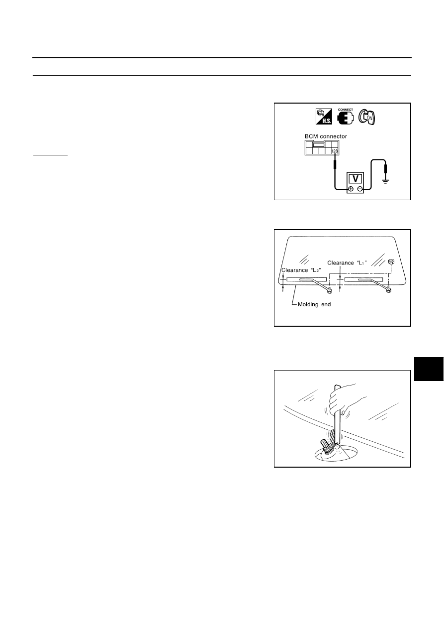
Lift the blade up and then set it down onto glass surface to set
the blade center to clearance “L1” and “L2” immediately before
tightening nut.

3.

Eject washer fluid. Turn on front wiper switch to operate front
wiper motor and then turn it “OFF”.

4.

Ensure that wiper blades stop within clearance “L1” and “L2”.

Tighten wiper arm nuts to specified torque.

Before reinstalling wiper arm, clean up the pivot area as illus-
trated. This will reduce possibility of wiper arm looseness.

Wash

: 0V (for 0.7sec.)

OFF

: Approx. 12V

SKIA4238E

Clearance “L1”

: 32.5 - 47.5 mm (1.280 - 1.870 in)

Clearance “L2”

: 24.5 - 39.5 mm (0.965 - 1.555 in)

Front wiper arm 
mounting nuts

: 20.6 - 26.5 N-m (2.1 - 2.7 kg-m, 
16 - 19 ft-lb)

SEL543TA

SEL024J

WW-20

WASHER SYSTEM

Removal and Installation for Front Wiper Motor and Linkage 

EKS001J7

REMOVAL

1.

Operate the front wiper motor, and stop it at the auto stop position.

2.

Remove wiper arm from the vehicle.

3.

Remove cowl top cover, refer to 

EI-20, "COWL TOP"

 .

4.

Disconnect front wiper motor connector.

5.

Remove bracket and front wiper motor assembly.

6.

Remove wiper link from wiper frame.

7.

Remove front wiper motor from the wiper frame.

INSTALLATION 

1.

Connect front wiper motor to connector. Turn the front wiper switch ON to operate front wiper motor, then
turn the front wiper switch OFF (auto stop).

2.

Disconnect front wiper motor connector.

3.

Install front wiper motor to the wiper frame.

4.

Install wiper link to the wiper frame and motor arm.

5.

Install front wiper motor assembly to the vehicle.

6.

Connect front wiper motor connector. Turn the front wiper switch ON to operate the front wiper motor, then
turn front wiper switch OFF (auto stop).

7.

Install bracket to the vehicle.

8.

Install cowl top cover, refer to 

EI-20, "COWL TOP"

 .

PKIA0318E

1.

Wiper link

2.

Wiper link

3.

Wiper frame

4.

Front wiper motor

PKIA0319E

WASHER SYSTEM

WW-21

C

D

E

F

G

H

I

J

L

M

A

B

WW

9.

Install wiper arm.

CAUTION:

Do not drop the front wiper motor or cause it to contact other parts.

Check the grease conditions of the motor arm and wiper link joint (at retainer). Apply grease if
necessary.

Washer Nozzle Adjustment 

EKS001J8

Adjust washer nozzle with suitable tool as shown in the figure at
left.

Unit: mm (in)

Washer Tube Layout 

EKS001J9

Adjustable range

±

10

°

PKIA0321E

Spray position

H (height)

L (length)

φ

 (spray point 

area)

A

202 (7.95)

548 (21.57)

80 (3.15)

B

313 (12.32)

301 (11.85)

80 (3.15)

C

260 (10.24)

27 (1.06)

80 (3.15)

D

172 (6.77)

146 (5.75)

80 (3.15)

E

339 (13.35)

302 (11.89)

80 (3.15)

F

181 (7.13)

500 (19.69)

80 (3.15)

PKIA0320E

PKIA0322E

WW-22

WASHER SYSTEM

Removal and Installation for Washer Nozzle 

EKS001JA

REMOVAL

1.

Push washer nozzle firmly toward either left or right to pull out.

2.

Remove washer hose from washer nozzle.

INSTALLATION

1.

After connecting washer hose, press nozzle from cowl top cover
surface.

2.

Assemble nozzle and socket.

3.

Adjust nozzle injection position.

Inspection for Washer Nozzle 

EKS001JB

CHECK VALVE

Blow air in the injection direction, and check that air flows only
one way. Make sure that the reverse direction (inhale) is not
possible. 

Wiper and Washer Switch Circuit Check 

EKS001JC

INSPECTION OF SWITCH CIRCUIT

Check continuity between each terminal when wiper washer switch
is operating using a circuit tester.

SKIA0108J

PKIA0324E

PKIA0323E

Operation interval (intermittent wiper with vehi-

cle speed detection function)

Resistance value (k

)

1 [Interval (Max.)]

0.964

2

0.659

3

0.325

4 [Interval (Min.)]

0.008

PKIA0325E


Content   ..  831  832  833  834   ..