Infiniti F50. Manual - part 821


  Index      Infiniti     Infiniti F50 - service repair manual 2006 year


Search            


Content   ..  819  820  821  822   ..


Infiniti F50. Manual - part 821


ELECTRICALLY CONTROLLED POWER STEERING SYSTEM

STC-9

[EPS]

C

D

E

F

H

I

J

K

L

M

A

B

STC

10. 

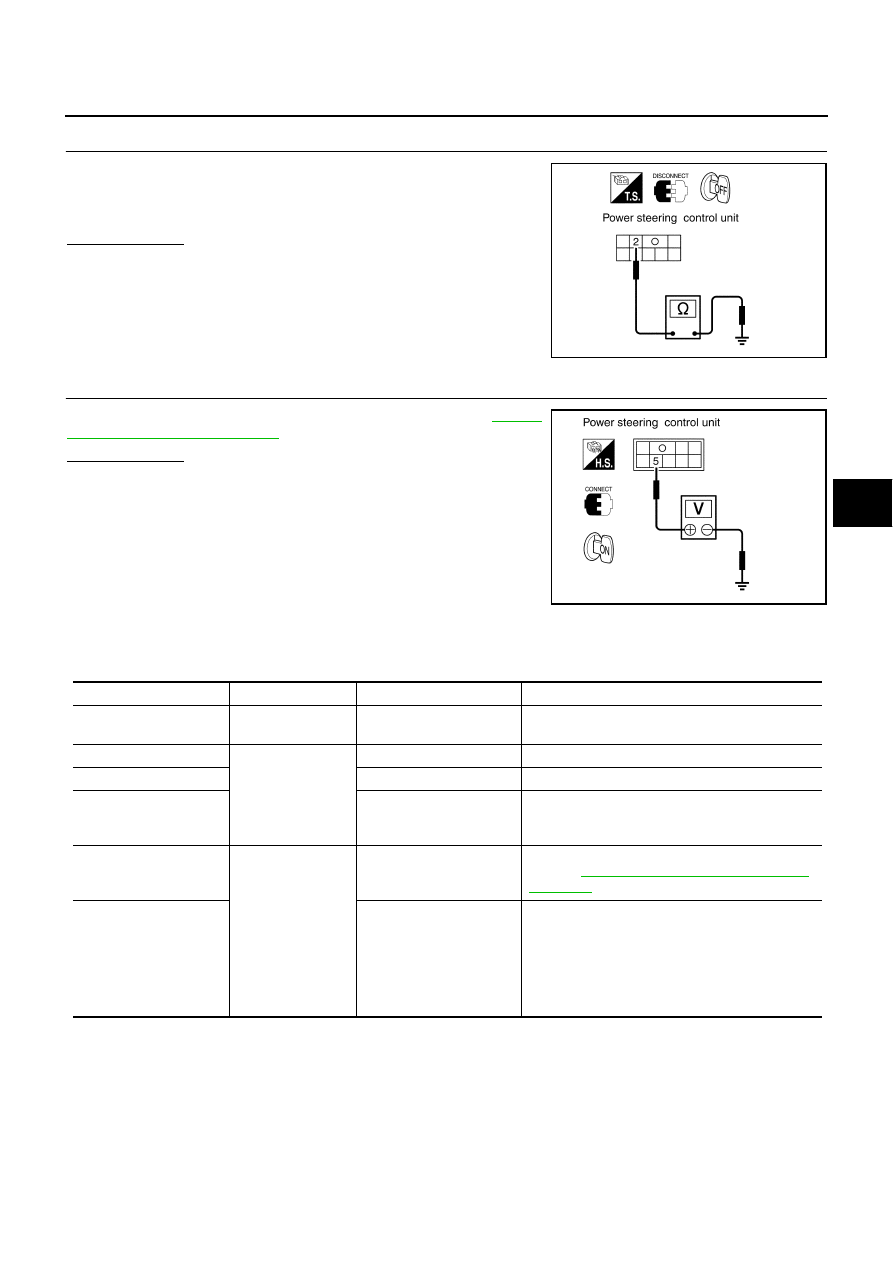
POWER STEERING CONTROL UNIT GROUND INSPECTION

Check for continuity between the power steering control unit terminal
2 (B) and body ground.

Is the result OK?

OK

>> GO TO 11.

NG

>> Repair or replace harness.

11. 

ENGINE REVOLUTION SIGNAL INSPECTION

Check power steering control unit terminal 5 (W/G),. Refer to 

STC-9,

"Control Unit Inspection Table"

 .

Is the result OK?

OK

>> GO TO 1.

NG

>> Check harness between ECM and control unit or ECM.

Repair or replace harness if necessary.

Control Unit Inspection Table

EGS0007Z

The standard values (voltage), measured with an analog tester in contact with control unit terminal, are shown
below:

 2 (B) - Body ground

: Continuity should exist

SGIA0051E

SGIA0052E

Inspection terminal

Condition

Application

Standard

Power steering control 

unit

1

Ignition switch ON

Power 

Battery voltage (approx. 12V)

2

Ground

0V

3

Vehicle speed signal

When the speed is very low, the voltage fluctuates 
between approximately 0V and approximately 5V 
or higher.

5

Engine running

Engine revolution signal

Measure the tachometer drive signal.
Refer to  

EC-99, "ECM Harness Connector Termi-

nal Layout"


7

Solenoid valve

Normal

0 km/h ((0 MPH)   

: Approx. 4.4 - 6.6V

100 km/h (62 MPH): Approx. 2.4 - 3.6V

When the fail-safe function is activated:

0 - 1,500 rpm      

: Approx. 4.4 - 6.6V

1,500 - 3,000 rpm  : Approx. 3.5V
3,000 rpm or more: Approx. 2.1V

STC-10

[EPS]

ELECTRICALLY CONTROLLED POWER STEERING SYSTEM

WT-1

ROAD WHEELS & TIRES

E  SUSPENSION

CONTENTS

C

D

F

G

H

I

J

K

L

M

SECTION 

A

B

WT

ROAD WHEELS & TIRES

PREPARATION ........................................................... 2

Special Service Tool  ................................................. 2
Commercial Service Tools ........................................ 2

NOISE, VIBRATION AND HARSHNESS (NVH) 
TROUBLESHOOTING ................................................ 3

NVH Troubleshooting Chart  ..................................... 3

ROAD WHEEL ............................................................ 4

Inspection ................................................................. 4

ALUMINUM WHEEL  ............................................. 4
STEEL WHEEL  ..................................................... 4

ROAD WHEEL TIRE ASSEMBLY  .............................. 5

Balancing Wheels (Bonding Weight Type)  ............... 5

REMOVAL ............................................................. 5
WHEEL BALANCE ADJUSTMENT  ...................... 5

Rotation .................................................................... 6

LOW TIRE PRESSURE WARNING SYSTEM ............ 7

System Components  ................................................ 7
System Description  .................................................. 7

TRANSMITTER ..................................................... 7
ANTENNA ............................................................. 7
TIRE PRESSURE WARNING CONTROL UNIT 

..... 8

VEHICLE INFORMATION DISPLAY  ..................... 8

TROUBLE DIAGNOSES  ............................................ 9

Wiring Diagram  ........................................................ 9
ID Registration Procedure  ...................................... 13

ID REGISTRATION WITH TRANSMITTER 
ACTIVATION TOOL  ............................................ 13
ID REGISTRATION WITHOUT TRANSMITTER 
ACTIVATION TOOL  ............................................ 14

Transmitter Wake Up Operation ............................. 14

WITH TRANSMITTER ACTIVATION TOOL ........ 14

Self-Diagnosis ........................................................ 15

DESCRIPTION .................................................... 15
FUNCTION .......................................................... 15
CONSULT-II ........................................................ 15

How to Perform Trouble Diagnosis for Quick and 
Accurate Repair  ..................................................... 17

INTRODUCTION ................................................. 17
WORK FLOW  ...................................................... 17

Preliminary Check  .................................................. 18
Malfunction Code/Symptom Chart .......................... 19

TROUBLE DIAGNOSIS FOR SELF-DIAGNOSTIC 
ITEMS ........................................................................ 20

Inspection 1: Transmitter or Low Tire Pressure 
Warning Control Unit  .............................................. 20

MALFUNCTION CODE NO. 21, 22, 23 OR 24 ... 20

Inspection 2: Transmitter - 1  ................................... 20

MALFUNCTION CODE NO. 31, 32, 33, 34, 41, 
42, 43, 44, 45, 46, 47 OR 48  ............................... 20

Inspection 3: Transmitter - 2  ................................... 21

MALFUNCTION CODE NO. 35, 36, 37 OR 38 ... 21

Inspection 4: Low Tire Pressure Warning Control 
Unit ......................................................................... 21

MALFUNCTION CODE NO. 51 ........................... 21

TROUBLE DIAGNOSIS FOR SYMPTOMS  .............. 22

Inspection 1: Warning Lamp Does Not Come On 
When Ignition Switch Is Turned On.  ....................... 22
Inspection 2: Warning Lamp Stays On When Ignition 
Switch Is Turned On.  .............................................. 23
Inspection 3: Warning Lamp Blinks When Ignition 
Switch Is Turned On.  .............................................. 24
Inspection 4: Hazard Warning Lamp Blinks When 
Ignition Switch Is Turned On.  ................................. 24
Inspection 5: “TIRE PRESSURE” Information In 
Display Does Not Exist.  .......................................... 24
Inspection 6: ID Registration Can Not Be Completed ... 25

REMOVAL AND INSTALLATION  ............................. 26

Transmitter ............................................................. 26

REMOVAL ........................................................... 26
INSTALLATION ................................................... 26

SERVICE DATA  ........................................................ 28

Road Wheel ............................................................ 28
Tire ......................................................................... 28

WT-2

PREPARATION

PREPARATION

PFP:00002

Special Service Tool

EES000CZ

The actual shapes of Kent-Moore tools may differ from those of special service tools illustrated here.

Commercial Service Tools

EES000N6

Tool number 
(Kent-Moore No.)
Tool name

Description

(J45295)
Transmitter activation tool

ID registration

SEIA0051E

Tool name

Description

Power tool

Removing wheel nuts

PBIC0190E


Content   ..  819  820  821  822   ..