Infiniti F50. Manual - part 768
AUTOMATIC DRIVE POSITIONER
SE-63
C
D
E
F
G
H
J
K
L
M
A
B
SE
3.
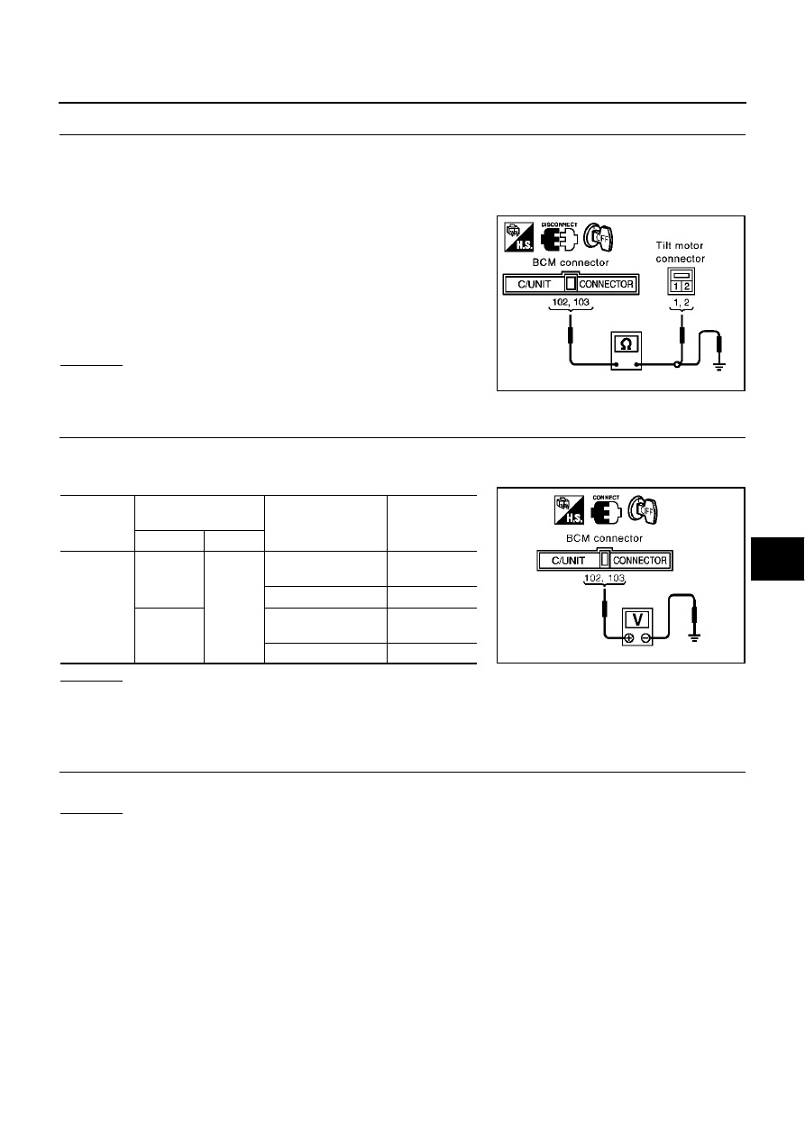
CHECK HARNESS CONTINUITY
1.
Turn ignition switch OFF.
2.
Disconnect BCM connector and tilt motor connector.
3.
Check continuity between BCM connector M4 terminals 102 (P), 103 (R/B) and tilt motor connector M58
terminals 1 (R/B), 2 (P).
4.
Check continuity between BCM connector M4 terminals 102 (P),
103 (R/B) and ground.
OK or NG
OK
>> GO TO 4.
NG
>> Repair or replace harness between BCM and tilt motor.
4.
CHECK BCM OUTPUT SIGNAL
1.
Connect BCM connector and tilt motor connector.
2.
Check voltage between BCM connector.
OK or NG
OK
>> Replace tilt motor.
NG
>> Replace BCM.
Seat Sliding Sensor Circuit Inspection
EIS0041T
1.
CHECK SLIDING SENSOR MECHANISM
Check the operation malfunction caused by sliding rail deformation or parts are loose.
OK or NG
OK
>> GO TO 2.
NG
>> Repair the malfunctioning part and check again.
102 (P) – 2 (P)
: Continuity should exist.
103 (R/B) – 1 (R/B)
: Continuity should exist.
102 (P) – Ground
:Continuity should not exist.
103 (R/B) – Ground
:Continuity should not exist.
PIIA3266E
Connector
Terminals
(Wire color)
Condition
Voltage (V)
(Approx.)
(+)
(–)
M4
102 (P)
Ground
Tilt switch
(DOWN operation).
Battery voltage
Tilt switch OFF.
0
103 (R/B)
Tilt switch
(UP operation).
Battery voltage
Tilt switch OFF.
0
PIIA4385E