Infiniti F50. Manual - part 752
TROUBLE DIAGNOSIS FOR SYMPTOMS
SCS-25
C
D
F
G
H
I
J
K
L
M
A
B
SCS
TROUBLE DIAGNOSIS FOR SYMPTOMS
PFP:00007
Inspection 5: Hard or Soft Feel
EES000EW
1.
SELF-DIAGNOSTICS INSPECTION
●
Disconnect control unit connector and shock absorber actuator connector, then re-connect them.
●
Perform self-diagnosis to check that proper test results are obtained.
Inspection results OK?
OK
>> GO TO 2.
NG
>> Check and repair detected area.
2.
CHECK SHOCK ABSORBER ACTUATOR OPERATION
●
Set the diagnostic system in the self-diagnosis mode.
●
Depress parking brake pedal.
●
Set select switch to “AUTO”, then move vehicle body up and down to check that dampening force of each
shock absorber is high. Brake pedal should be released during tests.
●
Set select lever to “SPORT”, then move vehicle body up and down to check that dampening force of each
shock absorber is high.
Inspection results OK?
OK
>> GO TO 11.
NG
>> GO TO 3.
3.
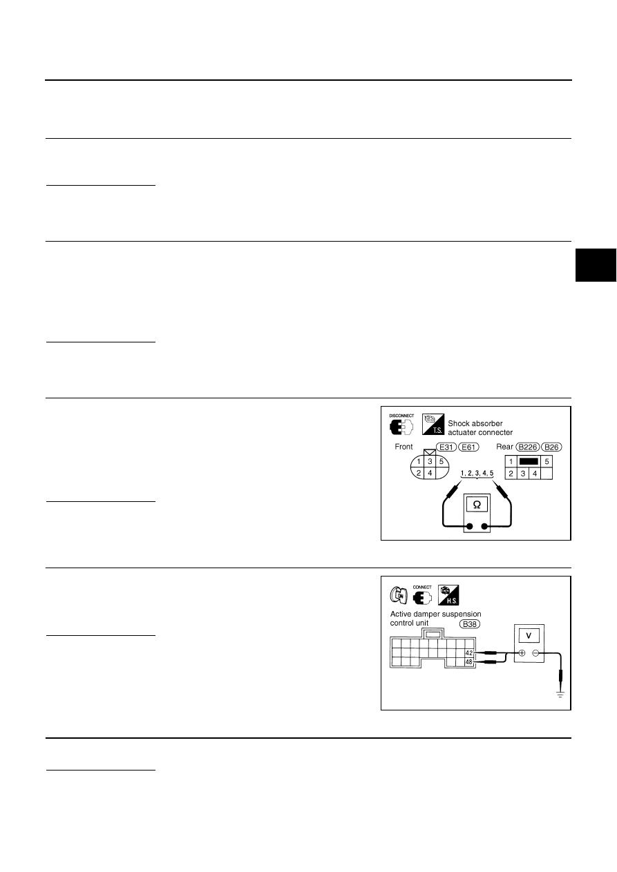
CHECK SHOCK ABSORBER ACTUATOR
●
Measure resistance between shock absorber actuator terminals.
Inspection results OK?
OK
>> GO TO 4.
NG
>> Replace actuator.
4.
CHECK CONTROL UNIT OUTPUT SIGNAL
●
Measure voltage between control unit connector terminals 42 (L/
R), 48 (B/R) and body ground.
Inspection results OK?
OK
>> GO TO 6.
NG
>> GO TO 5.
5.
CHECK HARNESS CONNECTOR
●
Check continuity between control unit and shock absorber actuator terminals.
Inspection results OK?
OK
>> Replace control unit
NG
>> Replace harness connector.
Front
1,2,4,5 - 3
: Approx. 12
Ω
Rear
1,3,4,5 - 2
: Approx. 12
Ω
SEIA0284E
42 (L/R),48 (B/R) - Body ground
: Battery voltage
SEIA0285E