Infiniti F50. Manual - part 743


  Index      Infiniti     Infiniti F50 - service repair manual 2006 year


Search            


Content   ..  741  742  743  744   ..


Infiniti F50. Manual - part 743


CHARGING SYSTEM

SC-19

C

D

E

F

G

H

I

J

L

M

A

B

SC

Removal and Installation 

EKS000A9

REMOVAL 

1.

Remove battery. Refer to 

SC-8, "Removal and Installation"

 .

2.

Remove air intake duct. Refer to 

EM-15, "AIR CLEANER AND AIR DUCT"

  in “ENGINE MECHANICAL

(EM)” section. 

3.

Remove alternator, water pump and A/C compressor belt. Refer to 

EM-13, "Removal and Installation"

  in

“ENGINE MECHANICAL (EM)” section.

4.

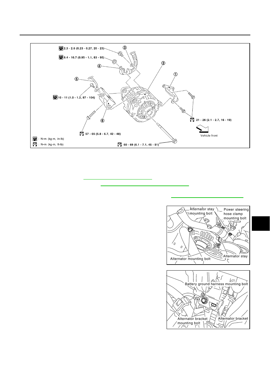
Remove alternator mounting bolts.

5.

Remove power steering hose clamp mounting bolt.

6.

Remove alternator stay mounting bolts and alternator stay.

7.

Remove battery ground harness mounting bolt.

8.

Remove alternator bracket mounting bolts and alternator
bracket.

PKIA2163E

1.

Alternator stay

2.

Alternator

3.

Alternator ground harness

4.

Alternator B terminal

5.

Battery ground harness

6.

Alternator  Bracket

PKIA2210E

PKIA2211E

SC-20

CHARGING SYSTEM

9.

Disconnect alternator connector.  

10. Remove B terminal  nut.

11. Remove alternator ground harness mounting bolt.

12. Remove power steering oil reservoir tank mounting bolts, then

slide power steering oil reservoir tank.

13. Remove alternator assembly from vehicle upper side.

INSTALLATION 

Install in the reverse order of removal, taking care of the following point.

Install alternator, and check tension of belt. Refer to 

EM-12, "Checking Drive Belts"

  in “ENGINE

MECHANICAL (EM)” section.

CAUTION:

Be sure to tighten B terminal nut carefully.

PKIA2212E

PKIA1810E

B terminal nut:

 : 9.4 - 10.7 N·m (0.95 - 1.1 kg-m, 83 - 95 in-lb)

Alternator ground harness mounting bolt:

 : 2.3 - 2.6 N·m (0.23 - 0.27 kg-m, 20 - 23 in-lb)

Battery ground harness mounting bolt:

 : 10 - 11 N·m (1.0 - 1.2 kg-m, 87 - 104 in-lb)

Power steering hose clamp mounting bolt:

 : 7.9 - 10.7 N·m (0.8 - 1.1 kg-m, 70 - 95 in-lb)

Power steering oil reservoir tank mounting bolt:

 : 16 - 20 N·m (1.6 - 2.0 kg-m, 12 - 15 ft-lb)

Alternator bracket mounting bolt:

 : 57 - 65 N·m (5.8 - 6.7 kg-m, 42 - 48 ft-lb)

Alternator mounting bolt (upper side):

 : 60 - 69 N·m (6.1 - 7.1 kg-m, 45 - 51 ft-lb)

Alternator stay mounting bolt:

 : 21 - 26 N·m (2.1 - 2.7 kg-m, 16 - 19 ft-lb)

Alternator mounting bolt (lower side):

 : 21 - 26 N·m (2.1 - 2.7 kg-m, 16 - 19 ft-lb)

CHARGING SYSTEM

SC-21

C

D

E

F

G

H

I

J

L

M

A

B

SC

Disassembly and Assembly

EKS000AA

PKIA1824E

1.

Pulley

2.

Front cover

3.

Front bearing

4.

Retainer

5.

Rotor

6.

Rear bearing

7.

Stator

8.

IC voltage regulator assembly

9.

Diode assembly

10.

Rear cover

Through bolt:

 : 3.5 - 5.3 N·m (0.36 - 0.54 kg-m, 31 - 47 in-lb)

Pulley nut:

 : 99 - 137 N·m (10.1 - 14.0 kg-m, 73 - 101 ft-lb)

SC-22

STARTING SYSTEM

STARTING SYSTEM 

PFP:00011

System Description 

EKS000AB

Power is supplied at all times

through 50A fusible link (letter G, located in the fuse, fusible link and relay box).

to ignition switch terminal 1

With the ignition switch in the  START position, power is supplied

from ignition switch terminal 4

to park/neutral position relay terminal 7.

Ground is supplied with the selector lever in the P or N position

to TCM terminal 48 through park/neutral position relay terminals 1 and 2 

from body grounds E24 and E44.

Then park/neutral position switch is energized and power is supplied

from park/neutral position relay terminal 6

to starter motor harness connector terminal 1.

The starter motor plunger closes and provides a closed circuit between the battery and starter motor. The
starter motor is grounded to the engine block. With power and ground supplied, cranking occurs and the
engine starts.


Content   ..  741  742  743  744   ..