Infiniti F50. Manual - part 740
 

  Index      Infiniti     Infiniti F50 - service repair manual 2006 year


Search            


Content   ..  738  739  740  741   ..


Infiniti F50. Manual - part 740


BATTERY

SC-7

C

D

E

F

G

H

I

J

L

M

A

B

SC

1.

Turn off all loads on the vehicle electrical system. Clean or repair
as necessary.

2.

Visually inspect the battery, battery terminals and cable ends
with ignition switch in “OFF” position.
NOTE:
The contact surface between the battery terminals, cable ends
and tester leads must be clean for a valid test. A poor connec-
tion will prevent testing and a “CHECK CONNECTION” mes-
sage will appear during the test procedures. If this occurs, clean
the battery post and terminals, reconnect them and restart the
test.

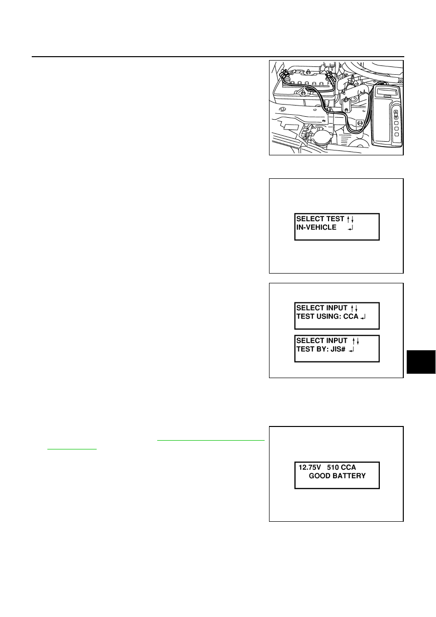
3.

Connect the red tester lead clamp to the positive battery termi-
nal, and the black to the negative terminal.

4.

The tester will turn on automatically. Using the arrow keys,
select “IN VEHICLE” on the tester and then press the “ENTER”
key.

5.

Locate the battery type and rating stamped or written on the top
case of the battery to be tested.
NOTE:
The battery type and rating will have either of the following.
CCA: Cold Cranking Amps (490 CCA, 550 CCA, etc.)
JIS: Japanese Industrial Standard.
Battery is stamped with a number such as:
80D26L: 80 (rank of output), D (physical size-depth), 26 (width
in cm). The last character L (post configuration) is not input into
the tester.
The tester requires the rating for the battery be entered exactly
as it is written or stamped on the battery. Do not attempt a CCA
conversion for JIS stamped batteries. JIS must be input directly.

6.

Using the arrow and “ENTER” keys alternately, select the battery type and rating.

NOTE:
The tester lists five choices; CCA, JIS, IEC, DIN, and EN. Only use CCA or JIS.

7.

Press “ENTER” to begin the test. Diagnosis results are dis-
played on the tester. Refer to 

SC-8, "DIAGNOSTIC RESULT

ITEM CHART"

 .

SEL404X

SEL405X

SEL406X

SEL407X

SC-8

BATTERY

8.

Press “ENTER”, then test output code is displayed. Record the
test output code on the repair order.

9.

Toggle back to the “DIAGNOSTIC SCREEN” for test results.

NOTE:

If necessary, the tester will ask the user to determine if the bat-
tery has just been charged. Choose the appropriate selection by
pressing the up or down arrow button and then press the
“ENTER” button to make the selection.

When testing a battery installed in a vehicle that has recently
been driven, select “BEFORE CHANGE”.

If the battery has just been slow charged due to a “CHARGE &
RETEST” decision by the tester, and the tester asks the user “BEFORE CHARGE/AFTER CHARGE”,
select “AFTER CHARGE”.

DIAGNOSTIC RESULT ITEM CHART

Removal and Installation 

EKS000A5

Observe the following to ensure proper servicing.

CAUTION:

When removing, remove negative terminal first. But for
installation, install positive terminal first.

Tighten parts to the specified torque shown below.

SEL576X

Diagnostic item

Service procedure

GOOD BATTERY

Battery is OK, go to “Trouble Diagnosis”, “STARTING SYSTEM”. Refer to 

SC-6, "Trouble 

Diagnosis with Battery/Starting/Charging System Tester"

 .

REPLACE BATTERY

Replace battery.
Before replacing battery, clean the battery cable clamps and battery posts. Perform battery 
test again with Battery/Starting/Charging system tester. If second test result is “Replace Bat-
tery”, then do so. Perform battery test again to confirm repair.

BAD CELL-REPLACE

Replace the battery. Perform battery test again with Battery/Starting/Charging system tester 
to confirm repair.

GOOD-RECHARGE

Perform the slow battery charging procedure. (Initial rate of charge is 10A for 12 hours.) Per-
form battery test again with Battery/Starting/Charging system tester.

CHARGE & RETEST

Perform the slow battery charging. (Initial rate of charge is 10A for 12 hours.)
Perform battery test again with Battery/Starting/Charging system tester to confirm repair.

NOTE:
If the tester asks the user “BEFORE CHARGE/AFTER CHARGE”, select “AFTER 
CHARGE”.

Battery fix frame mounting nut:

 : 3.5 - 5.3 N·m (0.36 - 0.54 kg-m, 31 - 46 in-lb)

Battery terminal nut:

 : 3.0 - 5.0 N·m (0.31 - 0.51 kg-m, 27 - 44 in-lb)

PKIA2352E

CHARGING SYSTEM

SC-9

C

D

E

F

G

H

I

J

L

M

A

B

SC

CHARGING SYSTEM 

PFP:00011

System Description 

EKS000A6

The alternator provides DC voltage to operate the vehicle's electrical system and to keep the battery charged.
The voltage output is controlled by the IC regulator.
Power is supplied at all times to alternator terminal 4 (S) through:

15A fuse [No. 56, located in the fuse, fusible link and relay block (J/B)]

Terminal B supplies power to charge the battery and operate the vehicle's electrical system. Output voltage is
controlled by the IC regulator at terminal 4 (S) detecting the input voltage.
The alternator is grounded to the engine block.
With the ignition switch in the ON or START position, power is supplied

10A fuse [No. 9, located in the fuse block (J/B) NO.1]

to combination meter terminal 59 for the charge warning lamp.

Ground is supplied to terminal 13 of the combination meter through terminal 3 (L) of the alternator. With power
and ground supplied, the charge warning lamp will illuminate. When the alternator is providing sufficient volt-
age with the engine running, the ground is opened and the charge warning lamp will go off.
If the charge warning lamp illuminates with the engine running, a malfunction is indicated.

SC-10

CHARGING SYSTEM

Wiring Diagram — CHARGE — 

EKS000A7

TKWM0227E


Content   ..  738  739  740  741   ..