Infiniti F50. Manual - part 728


  Index      Infiniti     Infiniti F50 - service repair manual 2006 year


Search            


Content   ..  726  727  728  729   ..


Infiniti F50. Manual - part 728


REAR FINAL DRIVE ASSEMBLY

RFD-17

C

E

F

G

H

I

J

K

L

M

A

B

RFD

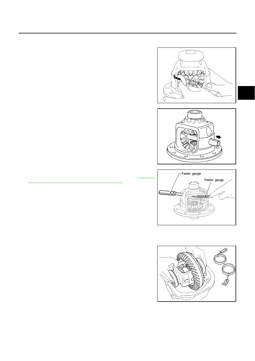
ADJUSTMENT OF DIFFERENTIAL CASE 
Thrust Washer Selection

1.

Install side gears, pinion mate gears, thrust washers  into differ-
ential case.

2.

Fit pinion mate shaft to differential case so that it meets lock pin
holes.

3.

Adjust clearance between rear face of side gear and thrust
washer by selecting side gear thrust washer. Refer to 

RFD-28,

"AVAILABLE SIDE GEAR THRUST WASHERS"

  .

Use two feeler gauges to prevent leaning of side gear as show-
ing, figure.

SIDE BEARING PRELOAD

A selection of carrier side bearing adjusting washers is required for successful completion of this procedure.

1.

Make sure all parts are clean. Also, make sure the bearings are
well lubricated with light oil or DEXRON

TM

  type automatic trans-

mission fluid.

2.

Place the differential carrier, with side bearings and bearing
races installed, into the final drive housing.

SPD552

SDIA0031J

Clearance between side gear thrust washer and dif-
ferential case

: 0.20mm (0.0079 in) less

SPD828

SPD527

RFD-18

REAR FINAL DRIVE ASSEMBLY

3.

Insert left and right side bearing adjusting washers in place
between side bearings and carrier.

4.

Install the side bearing caps in their correct locations and torque
the bearing cap retaining bolts.

5.

Turn the carrier several times to seat the bearings.

6.

Measure the turning torque of the carrier at the ring gear retain-
ing bolts with a spring gauge, J-8129.

7.

If the turning torque is not within the specifications, correct the
torque as follows:

If the turning torque is less than the specified range, install
washers of greater thickness.

If the turning torque is greater than the specification, install
thinner washers.

See the SDS section for washer dimensions and part num-
bers.  

8.

Record the total amount of washer thickness required for the
correct carrier side bearing preload.

9.

Remove the carrier from the final drive housing. Save the
selected washers for later use during the assembly of the final
drive unit.

SPD924

: 88 -  98 N·m (9.0 - 9.9kgm, 65 - 72 ft-lb)

SPD526

Specification

:34.2 - 39.2 N (3.5 - 4 kg, 7.7 - 8.8 lb)
of pulling force at the ring gear bolt

SPD194A

SPD772

Tool number:

HT72400000 (   –   )

S-PD344

REAR FINAL DRIVE ASSEMBLY

RFD-19

C

E

F

G

H

I

J

K

L

M

A

B

RFD

PINION GEAR HEIGHT

1.

Make sure all parts are clean and that the bearings are well
lubricated.

2.

Assemble the pinion gear bearings into the pinion preload shim
selector Tool, J34309.

Pinion front bearing; make sure the J34309-3 pinion front bear-
ing seat is secured tightly against the J34309-2 gauge anvil.
Then turn the pinion front bearing pilot, J34309-5, to secure the
bearing in its proper position.

Rear pinion bearing; the pinion rear bearing pilot, J34309-8, is
used to center the pinion rear bearing only. The pinion rear bear-
ing locking seat, J34309-4, is used to lock the bearing to the
assembly.

Installation of J34309-9 and J34309-16; place a suitable 2.5 mm
(0.098 in) thick plain washer between J34309-9 and J34309-16.
Both surfaces of J34309-9 and J34309-16 must be parallel with
a clearance of 2.5 mm (0.098 in).

3.

Install the pinion rear bearing inner race into the final drive hous-
ing. Then place the pinion preload shim selector Tool, J34309-1,
gauge screw assembly.

4.

Assemble the front pinion bearing inner race and the J34309-2
gauge anvil. Assemble them together with the J34309-1 gauge
screw in the final drive housing. Make sure that the pinion height
gauge plate, J34309-16, will turn a full 360 degrees. Tighten the
two sections together by hand.

SPD769

SPD197A

SPD893

SPD199A

RFD-20

REAR FINAL DRIVE ASSEMBLY

5.

Turn the assembly several times to seat the bearings.

6.

Measure the turning torque at the end of the J34309-2 gauge
anvil using torque wrench J-25765A.

7.

Place the J34309-11 “R200A” pinion height adapter onto the
gauge plate and tighten it by hand.

CAUTION:

Make sure all machined surfaces are clean.

Pinion Height Adjusting Washer Selection

1.

Now, position the side bearing discs, J25269-4, and arbor firmly
into the side bearing bores. Install the bearing caps and tighten
the cap bolts to proper torque.

SPD770

Turning torque specification

: 1.0 - 1.3 N·m( 0.11 - 0.13 kg-m, 9 - 11 in-lb)

SPD234A

SPD208A

SPD211A


Content   ..  726  727  728  729   ..