Infiniti F50. Manual - part 660


  Index      Infiniti     Infiniti F50 - service repair manual 2006 year


Search            


Content   ..  658  659  660  661   ..


Infiniti F50. Manual - part 660


INTERIOR ROOM LAMP

LT-107

C

D

E

F

G

H

I

J

L

M

A

B

LT

Bulb Replacement

EKS000WN

MAP LAMP (FRONT PERSONAL LIGHT) AND CONSOLE LAMP (CONSOLE LIGHT)
Map Lamp

1.

Remove the finisher using a clip driver or a suitable tool.

2.

Insert a thin screwdriver in the notch and remove the lens.

3.

Remove the screw and remove the shade.

4.

Remove the bulb.

Console Lamp

1.

Remove the front interior lamp. Refer to

LT-107, "FRONT INTERIOR LAMP"

 .

2.

Turn the console lamp bulb socket counterclockwise and unlock it.

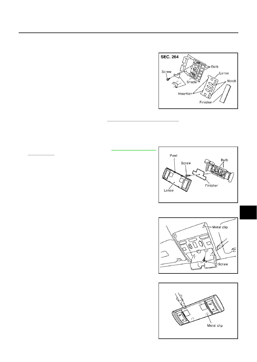
PERSONAL LAMP (REAR PERSONAL LIGHT)

1.

Remove the rear interior lamp. Refer to 

LT-107, "REAR INTE-

RIOR LAMP"

  in “Removal and Installation”.

2.

Unfold the tabs and remove the lens.

3.

Remove the shade mounting screw and remove the shade from
the personal lamp.

4.

Remove the bulb.

Removal and Installation

EKS000U4

FRONT INTERIOR LAMP

1.

Open the front interior lamp box and remove the screw.

2.

Insert a clip driver or a suitable tool and disengage the metal clip
fittings of the front interior lamp.

3.

Disconnect the connector and remove the front interior lamp.

REAR INTERIOR LAMP

1.

Using a clip driver or a suitable tool, press and remove the metal
clip of the rear interior lamp.

2.

Disconnect the rear interior lamp connector.

Map lamp (Front personal light)

: 12V 8W

PKIA0177E

Console lamp (Console light)

: 12V 1.4W

Personal lamp (Rear personal light)

: 12V 8W

PKIA0073E

PKIA0068E

PKIA0074E

LT-108

INTERIOR ROOM LAMP

IGNITION KEY HOLE ILLUMINATION

1.

Remove the lower instrument panel (driver side). Refer to 

IP-10,

"Removal and Installation"

  in “INSTRUMENT PANEL (IP)” sec-

tion.

2.

Turn the bulb socket counterclockwise and unlock it.

Ignition key hole illumination

: 12V 1.4W

PKIA0187E

STEP LAMP

LT-109

C

D

E

F

G

H

I

J

L

M

A

B

LT

STEP LAMP

PFP:26420

Component Parts and Harness Connector Location

EKS000ZR

SKIA3839E

LT-110

STEP LAMP

System Description

EKS0017S

POWER SUPPLY AND GROUND

Power is supplied at all times

to BCM terminal 105

through 10A fuse [No. 3, located in the fuse block (J/B) No. 1], and

to all step lamps terminal 1

through 10A fuse [No. 8, located in the fuse block (J/B) No. 1].

Ground is supplied to terminal 15 of driver door control unit through body grounds M24 and M114.
Ground is supplied to terminal 7 of passenger door control unit through body grounds M24 and M114.
Ground is also supplied to terminal 7 of rear LH door control unit and rear RH door control unit through body
grounds B17 and B57 or B217 and B256.

OPERATING PROCEDURE

BCM is connected to driver door control unit as DATA LINE A-3.
Then driver door control unit is connected to each door control unit. 
When any door switch is in OPEN position, ground is supplied

to BCM terminal 33, 37, 142, or 143

through driver side, passenger side, rear LH or RH door switch.

Then BCM sends a signal to the driver door control unit (LCU 01) to turn on step lamp. With ground supplied,
step lamp turns on.


Content   ..  658  659  660  661   ..