Infiniti F50. Manual - part 657


  Index      Infiniti     Infiniti F50 - service repair manual 2006 year


Search            


Content   ..  655  656  657  658   ..


Infiniti F50. Manual - part 657


INTERIOR ROOM LAMP

LT-95

C

D

E

F

G

H

I

J

L

M

A

B

LT

3. 

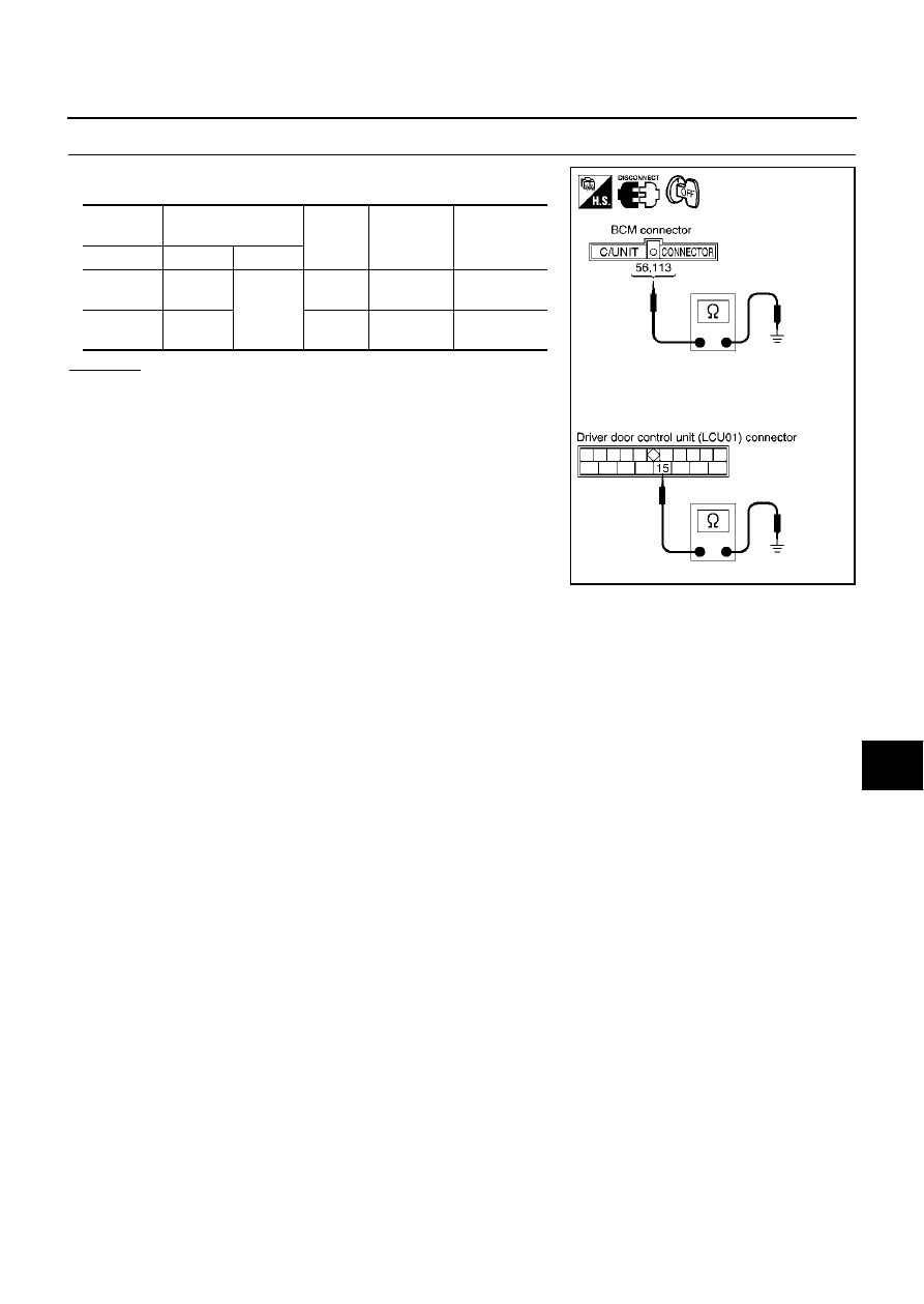
CHECK GROUND CIRCUIT

Check continuity between the following harness connector terminal
of the BCM and driver door LCU and body ground.

OK or NG

OK

>> Inspection end.

NG

>> Repair or replace harness.

Unit

Terminal

(Wire color)

Signal

Ignition 

switch

Continuity

Connector

(+)

(–)

BCM (M4)

56 (B),

 113 (B)

Body 

ground

Ground

Ignition 

switch OFF

Continuity 

should exist

Driver door 
LCU (D8)

15 (B)

Ground

Ignition 

switch OFF

Continuity 

should exist

SKIA3931E

LT-96

INTERIOR ROOM LAMP

CONSULT-II Function

EKS000X3

CONSULT-II has the display function for the work support, data monitor and active test for each part by
combining data receiving and sending via the communication line from the BCM.

CONSULT-II BASIC OPERATION PROCEDURE

1.

With the ignition switch OFF, connect “CONSULT-II” and “CON-
SULT-II CONVERTER” to the data link connector, then turn igni-
tion switch ON.

2.

Touch “START (NISSAN BASED VHCL)”.

3.

Touch “IVMS” on “SELECT SYSTEM” screen. If “IVMS” is not
indicated, go to 

GI-38, "CONSULT-II Data Link Connector (DLC)

Circuit"

 .

4.

Check the model specification, touch either “WITH SUNROOF”
or “WITHOUT SUNROOF”.

5.

Touch “OK”. If the selection is wrong, touch “CANCEL”.

IVMS diagnosis position

Diagnosis mode

Description

Interior illumination

Work support

Changes setting of each function.

Data monitor

Displays input data of the BCM and each LCU in real-time.

Active test

Operation of electrical loads can be checked by sending driving signal to them.

BCM part number

Displays BCM part No.

SHIA0179E

SKIA3098E

SKIA3783E

PIIA0184E

INTERIOR ROOM LAMP

LT-97

C

D

E

F

G

H

I

J

L

M

A

B

LT

6.

Select the desired part to be diagnosed on the “SELECT TEST ITEM” screen.

WORK SUPPORT
Operation procedure

1.

Touch “INTERIOR ILLUMINATION” on the “SELECT TEST ITEM” screen.

2.

Touch “WORK SUPPORT” on the “SELECT DIAG MODE” screen.

3.

Touch “SET INT-L LOGIC-TIM” or “SET I/L LGC-D-UNLCK” on the “SELECT WORK ITEM” screen.

4.

Touch “START”.

5.

Touch “NORMAL”/“MODE 1 - 3” of which setting is to be changed (for the interior lamp logic timer setting
only).

6.

Touch “CHANGE SET”.

7.

The setting will be changed and the current setting status will be displayed.

8.

Touch “END”.

Display item list

Refer to 

LT-93, "SETTING CHANGE FUNCTION"

 .

DATA MONITOR
Operation procedure

1.

Touch “INTERIOR ILLUMINATION” on the “SELECT TEST ITEM” screen.

2.

Touch “DATA MONITOR” on the “SELECT DIAG MODE” screen.

3.

Touch “ALL SIGNALS” or “SELECTION FROM MENU” on the “DATA MONITOR” screen.

4.

Touch “START”.

5.

When selected “SELECTION FROM MENU”, touch items to be monitored. When “ALL SIGNALS” is
selected all items will be monitored.

6.

Touch “RECORD” while monitoring and status of the item being monitored can be recorded. To stop
recording, touch “STOP”.

Display item list

ACTIVE TEST
Operation procedure

1.

Touch “INTERIOR ILLUMINATION” on the “SELECT TEST ITEM” screen.

MAIN SIGNALS

Monitors the main items.

SELECTION FROM MENU

Selects and monitors the items.

Monitored item [“OPERATION OR UNIT”]

Description

IGN ON SW

[ON/OFF]

Displays status of the ignition switch as judged from the ignition switch signal. 
(Key is in ON position: ON/Key is in ACC or OFF position: OFF)

DOOR SW-DR

[ON/OFF]

Displays status of the driver door as judged from the driver door switch signal. 
(Door is open: ON/Door is closed: OFF)

DOOR SW-AS

[ON/OFF]

Displays “Door open (ON)/door closed (OFF)” status judged from the door switch 
AS signal.

DOOR SW-RR

[ON/OFF]

Displays “Door open (ON)/door closed (OFF)” status judged from the door switch 
RR signal.

DOOR SW-RL

[ON/OFF]

Displays “Door open (ON)/door closed (OFF)” status judged from the door switch 
RL signal.

HD/LMP 1ST SW

[ON/OFF]

Displays status of the lighting switch as judged from the lighting switch signal. 
(OFF or AUTO position: OFF/Other than OFF and AUTO position: ON)

IGN KEY SW

[ON/OFF]

Displays “Key inserted (ON)/key withdrawn (OFF)” status judged from the key 
remainder detection switch signal.

IGN ACC SW

[ON/OFF]

Displays “Ignition ON or ACC (ON)/ignition OFF (OFF)” status judged from the 
ignition switch signal.

LOCK SIG-DR

[LOCK/UNLK]

Displays “Door locked (LOCK)/door unlocked (UNLK)” status judged from the 
locking detection switch DR signal.

LT-98

INTERIOR ROOM LAMP

2.

Touch “ACTIVE TEST” on the “SELECT DIAG MODE” screen.

3.

Touch item to be tested and check operation of the selected item.

4.

Touch “STOP” while testing and the operation will be stopped.

Display item list

CAUTION:

Active test should be conducted with the lamp switch in AUTO position.

On Board Diagnosis

EKS000X4

ON BOARD DIAGNOSTIC RESULTS INDICATOR LAMP.

Front map lamps and step lamps (all seats) act an the indicators for the on board diagnosis.

DIAGNOSIS ITEM

SWITCH MONITOR

Perform the diagnosis on the switch system to each control unit.

How to perform switch monitor

Test items

Display on CONSULT-II 

screen

Description

Map lamp output

FR PERSONAL LAMP

Map lamp can be operated by any ON-OFF operation of lights.

Personal lamp output

RR PERSONAL LAMP

Personal lamp can be operated by any ON-OFF operation of lights.

Ignition key hole illumination 
output

KEY RING ILLUM

Ignition key hole illumination can be operated by any ON-OFF operation 
of lights.

Diagnosis item

Description

Switch monitor

Checks for malfunction in switch systems that input to BCM and each LCU.

SIIA0411E


Content   ..  655  656  657  658   ..