Infiniti F50. Manual - part 622
IVMS (LAN)
LAN-17
[LAN]
C
D
E
F
G
H
I
J
L
M
A
B
LAN
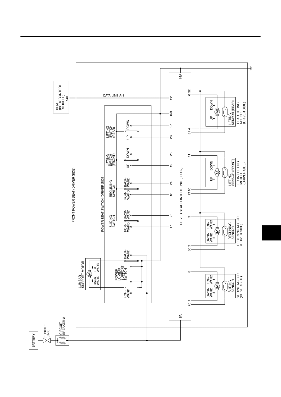
Schematic - LCU02 -
EKS001PN
DRIVER'S SEAT CONTROL UNIT
TKWM0118E
|
|
|
IVMS (LAN) LAN-17 [LAN] C D E F G H I J L M A B LAN Schematic - LCU02 - EKS001PN DRIVER'S SEAT CONTROL UNIT TKWM0118E |