Index Infiniti Infiniti F50 - service repair manual 2006 year
Search
Content .. 596 597 598 599 ..
Infiniti F50. Manual - part 598
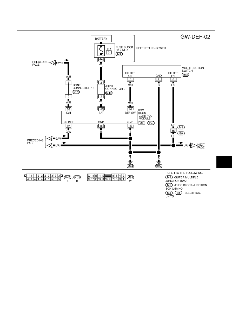
REAR WINDOW DEFOGGER
GW-63
C
D
E
F
G
H
J
K
L
M
A
B
GW
TIWM0207E