Index Infiniti Infiniti F50 - service repair manual 2006 year
Search
Content .. 586 587 588 589 ..
Infiniti F50. Manual - part 588
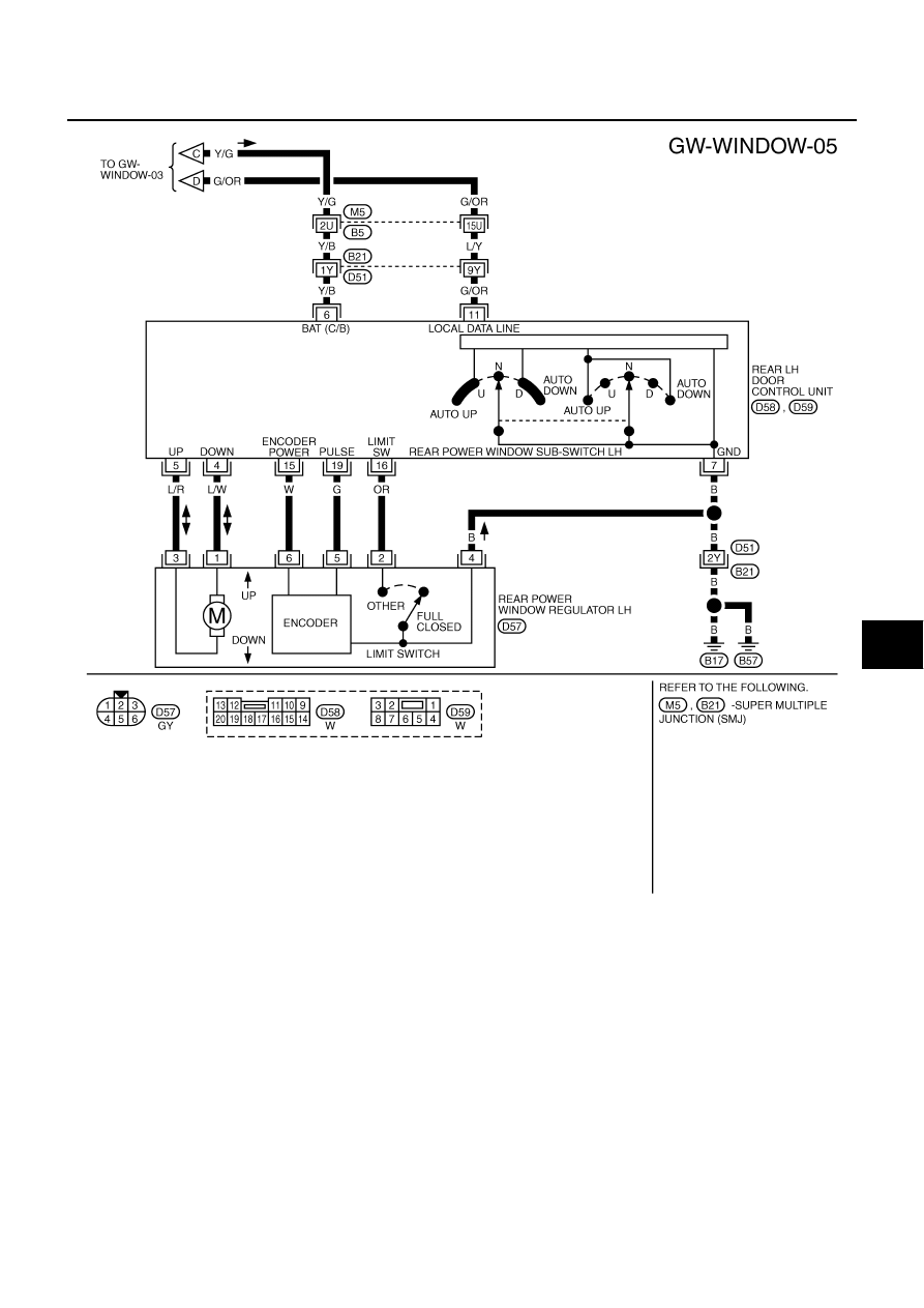
POWER WINDOW SYSTEM
GW-23
C
D
E
F
G
H
J
K
L
M
A
B
GW
TIWM0212E