Infiniti F50. Manual - part 545


  Index      Infiniti     Infiniti F50 - service repair manual 2006 year


Search            


Content   ..  543  544  545  546   ..


Infiniti F50. Manual - part 545


CYLINDER HEAD

EM-67

C

D

E

F

G

H

I

J

K

L

M

A

EM

2.

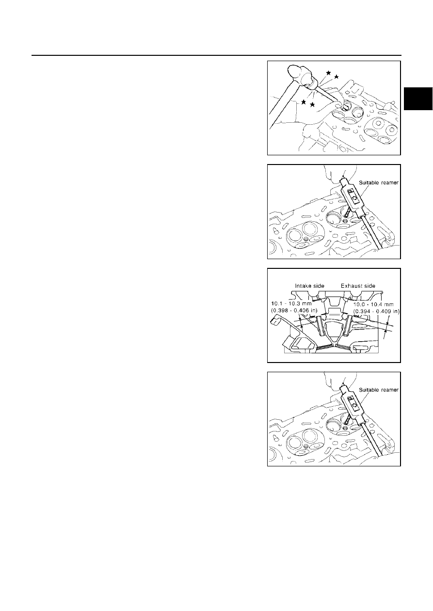
Drive out valve guide with a press [under a 20 kN (2 ton, 2.2 US
ton, 2.0 lmp ton) pressure] or hammer and suitable tool.

CAUTION:

Cylinder head contains heat, when working wear protective
equipment to avoid getting burned.

3.

Ream cylinder head valve guide hole.

4.

Heat cylinder head to 110 to 130

°

C (230 to 266

°

F) by soaking in

heated oil.

5.

Press valve guide from camshaft side to dimensions as in illus-
tration.

CAUTION:

Cylinder head contains heat, when working wear protective
equipment to avoid getting burned.

6.

Using valve guide reamer, apply reamer finish to valve guide.

SEM931C

Valve guide hole diameter (for service parts)

Intake and exhaust:

10.175 - 10.196 mm (0.4006 - 0.4014 in)

SEM932C

PBIC0078E

Standard

Intake and exhaust:

 6.000 - 6.018 mm (0.2362 - 0.2369 in)

SEM932C

EM-68

CYLINDER HEAD

VALVE SEAT CONTACT

After confirming that the dimensions of valve guides and valves
are within specifications, perform this procedure. 

Apply prussian blue (or white lead) onto contacting surface of
valve seat to check the condition of the valve contact on the sur-
face.

Check if the contact area band is continuous all around the cir-
cumference.

If not, grind to adjust valve fitting and check again. If the contact-
ing surface still has N.G conditions even after the re-check,
replace valve seat.

VALVE SEAT REPLACEMENT

When valve seat is removed, replace with oversized (0.5 mm, 0.020 in) valve seat.
1.

Bore out old seat until it collapses. Boring should not continue beyond the bottom face of the seat recess
in cylinder head. Set the machine depth stop to ensure this.

2.

Ream cylinder head recess diameter for service valve seat.

Be sure to ream in circles concentric to the valve guide center.

This will enable valve seat to fit correctly.

3.

Heat cylinder head to 110 to 130

°

C (230 to 266

°

F) by soaking in

heated oil.

4.

Provide valve seats cooled well with dry ice. Force fit valve seat
into cylinder head.

CAUTION:

Avoid directly touching cold valve seats.

Cylinder head contains heat, when working wear protec-
tive equipment to avoid getting burned.

5.

Using valve seat cutter set and valve seat grinder, finish the seat
to the specified dimensions.

CAUTION:

When using valve seat cutter, firmly grip the cutter handle
with both hands. Then, press on the contacting surface all
around the circumference to cut in a single drive. Improper
pressure on with the cutter or cutting many different times
may result in stage valve seat. 

SBIA0322E

Oversize [0.5 mm (0.020 in)]:

Intake  37.500 - 37.516 mm (1.4764 - 1.4770 in)

Exhaust  32.700 - 32.716 mm (1.2874 - 1.2880 in)

SEM795A

SEM008A

SEM934C

CYLINDER HEAD

EM-69

C

D

E

F

G

H

I

J

K

L

M

A

EM

Grind to obtain the dimensions indicated in figure.

6.

Using compound, grind to adjust valve fitting. 

7.

Check again for normal contact.

VALVE SPRING SQUARENESS

Set try square along the side of valve spring and rotate the spring.
Measure the maximum clearance between the top face of spring and
try square.

If it exceeds the limit, replace valve spring.

VALVE SPRING DIMENSIONS AND VALVE SPRING PRESSURE LOAD

Check valve spring pressure at specified spring height.

CAUTION:

Do not remove valve spring seat from valve spring (parts for
assy).

If the dimensions exceed the standard, replace the valve spring.

SBIA0377E

SBIA0378E

Limit

: 2.0 mm (0.079 in)

PBIC0080E

Standard:

Free height 46.35 - 46.85 mm (1.8247 - 1.8444 in)

Installation height 33.8 mm (1.331 in)

Installation load 165- 189 N (16.8 - 19.3 kg, 37- 42 lb)

Height during valve open 24.4 mm (0.961 in)

Load with valve open 290- 330 N (29.6- 33.7 kg, 65 - 74 lb)

SEM113

EM-70

ENGINE ASSEMBLY

ENGINE ASSEMBLY

PFP:10001

Removal and Installation

EBS001K5

WARNING:

Situate vehicle on a flat and solid surface.

Place chocks at front and back of rear wheels.

For engines not equipped with engine slingers, attach proper slingers and bolts described in
PARTS CATALOG.

CAUTION:

Always be careful to work safely, avoid forceful or uninstructed operations.

Do not start working until exhaust system and engine coolant are cool enough.

If items or work required are not covered by the engine section, refer to the applicable sections.

Always use the support point specified for lifting.

Use either 2-point lift type or separate type lift as best you can. If board-on type is used for
unavoidable reasons, support at the rear axle jacking point with transmission jack or similar tool
before starting work, in preparation for the backward shift of center of gravity.

For supporting points for lifting and jacking point at rear axle, refer to 

GI-40, "Garage Jack and

Safety Stand"

 .

REMOVAL

Outline
After removal of transmission, lift up engine assembly to remove it from vehicle.
Preparation

1.

Release fuel pressure. Refer to 

EC-48, "FUEL PRESSURE RELEASE"

 .

2.

Remove engine cover and engine undercover with power tool.

PBIC0081E

1.

Rear engine mounting insulator

2.

Rear member

3.

LH engine mounting bracket

4.

Heat insulator

5.

LH engine mounting insulator

6.

RH engine mounting bracket

7.

Heat insulator

8.

RH engine mounting insulator


Content   ..  543  544  545  546   ..