Infiniti F50. Manual - part 536


  Index      Infiniti     Infiniti F50 - service repair manual 2006 year


Search            


Content   ..  534  535  536  537   ..


Infiniti F50. Manual - part 536


FUEL INJECTOR AND FUEL TUBE

EM-31

C

D

E

F

G

H

I

J

K

L

M

A

EM

FUEL INJECTOR AND FUEL TUBE

PFP:16600

Removal and Installation

EBS001LF

CAUTION:

Apply new engine oil when installing the parts that specified to do so in the figure.

Do not remove or disassemble parts unless instructed as shown in the figure.

REMOVAL

1.

Release fuel pressure. Refer to 

EC-48, "FUEL PRESSURE RELEASE"

 .

2.

Remove intake manifold upper with power tool. Refer to 

EM-17, "Removal and Installation"

 .

3.

Disconnect fuel injector sub harness connectors.

4.

Disconnect fuel damper assembly with hose from fuel tube RH and LH.

5.

Remove fuel injectors with fuel tube assembly.
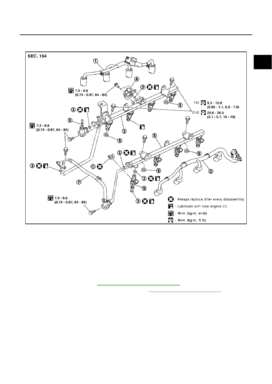
SBIA0363E

1.

Fuel injector sub harness (RH)

2.

Fuel tube assembly (RH)

3.

O-ring

4.

Fuel damper assembly (RH)

5.

Fuel injector sub harness (LH)

6.

Fuel tube assembly (LH)

7.

Fuel damper assembly, with hose

8.

Fuel feed damper assembly

9.

Insulator

10. Fuel 

injector

11.

Clip

EM-32

FUEL INJECTOR AND FUEL TUBE

6.

Expand and remove clips securing fuel injectors.

7.

Extract fuel injectors straight from fuel tubes.

Be careful not to damage injector nozzles during
removal.

Do not bump or drop fuel injectors.

INSTALLATION

1.

Carefully install O-rings, including the one used the fuel damper.

Lubricate O-rings by smearing new engine oil.

Be careful not to damage O-rings and surfaces for O-ring sealing with service tools, finger nails
or clips. Do not expand or twist O-rings.

Discard old clips; replace with new ones.

2.

Position clips in grooves on fuel injectors.

Make sure that protrusions of fuel injectors are aligned with cutouts of clips after installation.

3.

Align protrusions of fuel tubes with those of fuel injectors.

4.

After properly inserting fuel injectors, check to make sure that fuel tube protrusions are engaged with
those of fuel injectors, and that flanges of fuel tubes are engaged with clips.

5.

Tighten fuel tube assembly mounting bolts “a” to “c” in   illustra-
tion and in two steps.

6.

Install all removed parts in the reverse order of removal.

INSPECTION AFTER INSTALLATION
Check on Fuel Leakage

After installing fuel tubes, make sure there is no fuel leakage at connections in the following steps.

a) Apply fuel pressure to fuel lines with turning ignition switch ON (with engine stopped). Then check for

fuel leaks at connections.

b) Start the engine and rev it up and check for fuel leaks at connections.
NOTE:
Use mirrors for checking on invisible points.

CAUTION:

Do not touch the engine immediately after stopped, as engine becomes extremely hot.

SBIA0364E

1st step

 : 9.3 - 10.8 N·m (0.95 - 1.1 kg-m, 6.2 - 7.9 ft-lb)

2nd step

 : 20.6 - 26.5 N·m (2.1 - 2.7 kg-m, 16 - 19 ft-lb)

PBIC1002E

ROCKER COVER

EM-33

C

D

E

F

G

H

I

J

K

L

M

A

EM

ROCKER COVER

PFP:13264

Removal and Installation

EBS001LG

REMOVAL

1.

Refer to the followings for removal works related to left-bank. 

a.

Remove engine cover (with power tool) and air cleaner cover. Refer to 

EM-11, "Removal and Installation"

 .

b.

Remove air duct and air cleaner case assembly. Refer to 

EM-15, "Removal and Installation"

 .

c.

Remove bracket (installation parts for No.6 camshaft bracket).

d.

Move harness on upper rocker cover and its peripheral aside.

e.

Remove ignition coil. Refer to 

EM-28, "Removal and Installation"

 .

f.

Remove PCV valve hose from PCV valve.

2.

Refer to the followings for removal works related to right-bank.

a.

Remove engine cover (with power tool) and battery cover. Refer to 

EM-11, "Removal and Installation"

 .

b.

Move harness on upper rocker cover and its peripheral aside.

c.

Remove ignition coil 

EM-28, "Removal and Installation"

 .

d.

Remove PCV valve hose from PCV valve.

SBIA0385E

1.

Rocker cover (left bank)

2.

PCV valve

3.

O-ring

4.

Rocker cover gasket (left bank)

5.

Rocker cover (right bank)

6.

PCV valve

7.

O-ring

8.

Oil filler cap

9.

Oil catcher

10.

Rocker cover gasket (right bank)

EM-34

ROCKER COVER

3.

Loosen bolts in reverse order shown in the figure (with power
tool).

CAUTION:

Do not hold oil filler neck (right bank) not to damage it.

INSTALLATION

1.

Apply liquid gasket to joint part of cylinder head and camshaft
bracket following the below steps.

NOTE:
Illustration shows an example of left-bank side (zoomed in
shows No.1 camshaft bracket). Apply only to No.1 camshaft
bracket for right-bank side.

a.

Refer to illustration “a” to apply liquid gasket to joint part of No.1
and No.6 camshaft bracket and cylinder head.

b.

Refer to illustration “b” to apply liquid gasket in 90

°

 to illustration

“a”.
Use Genuine RTV Silicone Sealant or equivalent. Refer to

GI-46, "RECOMMENDED CHEMICAL PRODUCTS AND
SEALANTS"

 .

2.

Install rocker cover.

Check if rocker cover gasket is not dropped from installation
groove of rocker cover. 

3.

Tighten bolts in two steps separately in order numbers in illustration.

4.

Install in the reverse order of removal after this step. 

PBIC0027E

PBIC0028E

1st step

 : 1.0 - 3.0 N·m (0.1 - 0.31 kg-m, 9 - 26 in-lb)

2nd step

 : 7.4 - 9.3 N·m (0.75 - 0.95 kg-m, 66 - 82 in-lb)

PBIC0027E


Content   ..  534  535  536  537   ..