Index Infiniti Infiniti F50 - service repair manual 2006 year
Search
Content .. 506 507 508 509 ..
Infiniti F50. Manual - part 508
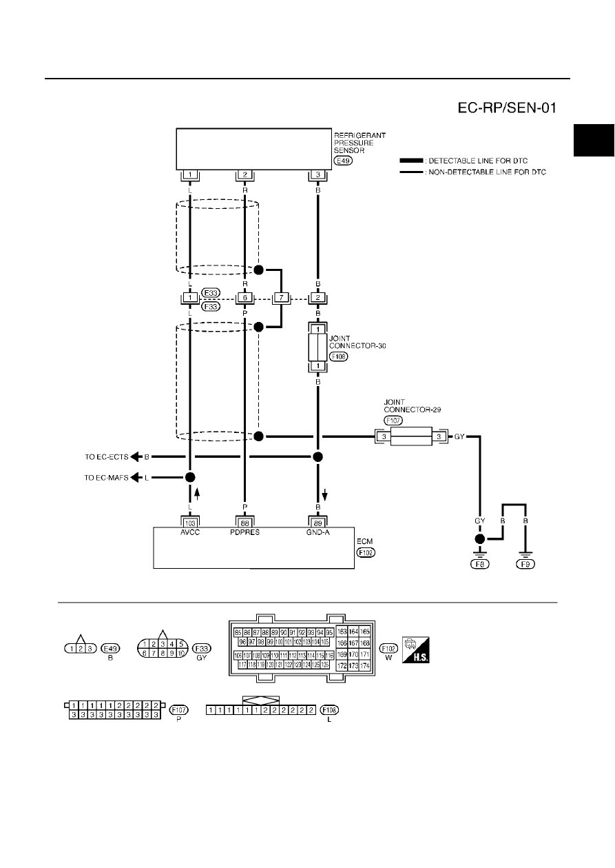
REFRIGERANT PRESSURE SENSOR
EC-673
C
D
E
F
G
H
I
J
K
L
M
A
EC
Wiring Diagram
EBS00MOH
TBWM0134E