Infiniti F50. Manual - part 428


  Index      Infiniti     Infiniti F50 - service repair manual 2006 year


Search            


Content   ..  426  427  428  429   ..


Infiniti F50. Manual - part 428


DTC P0452 EVAP CONTROL SYSTEM PRESSURE SENSOR

EC-353

C

D

E

F

G

H

I

J

K

L

M

A

EC

DTC Confirmation Procedure

EBS00MF0

NOTE:
If “DTC Confirmation Procedure” has been previously conducted, always turn ignition switch “OFF” and wait at
least 10 seconds before conducting the next test.
TESTING CONDITION:
Always perform test at a temperature of 5

°

C (41

°

F) or more.

 WITH CONSULT-II

1.

Start engine and warm it up to normal operating temperature.

2.

Turn ignition switch “OFF” and wait at least 10 seconds.

3.

Turn ignition switch “ON”.

4.

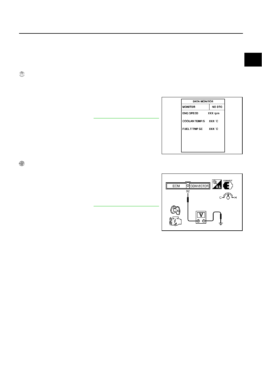
Select “DATA MONITOR” mode with CONSULT-II.

5.

Make sure that “FUEL T/TEMP SE” is more than 0

°

C (32

°

F).

6.

Start engine and wait at least 20 seconds.
If 1st trip DTC is detected, go to 

EC-355, "Diagnostic Procedure"

.

 WITH GST

1.

Start engine and warm it up to normal operating temperature.

2.

Check that voltage between ECM terminal 92 (Fuel tank temper-
ature sensor signal) and ground is less than 4.2V.

3.

Turn ignition switch “OFF” and wait at least 10 seconds.

4.

Start engine and wait at least 20 seconds.

5.

Select “MODE 7” with GST.
If 1st trip DTC is detected, go to 

EC-355, "Diagnostic Procedure"

.

SEF194Y

SEF340X

EC-354

DTC P0452 EVAP CONTROL SYSTEM PRESSURE SENSOR

Wiring Diagram

EBS00MF1

TBWM0132E

DTC P0452 EVAP CONTROL SYSTEM PRESSURE SENSOR

EC-355

C

D

E

F

G

H

I

J

K

L

M

A

EC

Specification data are reference values and are measured between each terminal and ground.

CAUTION:

Do not use ECM ground terminals when measuring input/output voltage. Doing so may result in dam-
age to the ECM's transistor. Use a ground other than ECM terminals, such as the ground.

Diagnostic Procedure

EBS00MF2

1. 

RETIGHTEN GROUND SCREWS

Loosen and retighten engine ground screws.

>> GO TO 2.

2. 

CHECK CONNECTOR

1.

Disconnect EVAP control system pressure sensor harness connector.

2.

Check sensor harness connector for water.

OK or NG

OK

>> GO TO 3.

NG

>> Repair or replace harness connector.

TER-

MINAL 

NO.

WIRE 

COLOR

ITEM

CONDITION

DATA (DC Voltage)

89

B

Sensor ground

[Engine is running]

Warm-up condition

Idle speed

Approximately 0V

103

L

Sensor power supply

[Ignition switch “ON”]

Approximately 5V

110

G

EVAP control system pres-
sure sensor

[Ignition switch “ON”]

Approximately 1.8 - 4.8V

PBIB0011E

Water should not exist.

PBIB0026E

EC-356

DTC P0452 EVAP CONTROL SYSTEM PRESSURE SENSOR

3. 

CHECK EVAP CONTROL SYSTEM PRESSURE SENSOR POWER SUPPLY CIRCUIT

1.

Turn ignition switch “ON”.

2.

Check voltage between EVAP control system pressure sensor
terminal 1 and ground with CONSULT-II or tester.

OK or NG

OK

>> GO TO 5.

NG

>> GO TO 4.

4. 

DETECT MALFUNCTIONING PART

Check the following.

Harness connectors B401, B251

Harness connectors B211, M141

Harness connectors M135, F105

Harness for open or short between EVAP control system pressure sensor and ECM

>> Repair harness or connectors.

5. 

CHECK EVAP CONTROL SYSTEM PRESSURE SENSOR GROUND CIRCUIT FOR OPEN AND 

SHORT

1.

Turn ignition switch “OFF”.

2.

Check harness continuity between EVAP control system pressure sensor terminal 3 and ECM terminal
89.
Refer to Wiring Diagram.

3.

Also check harness for short to ground and short to power.

OK or NG

OK

>> GO TO 7.

NG

>> GO TO 6.

6. 

DETECT MALFUNCTIONING PART

Check the following.

Harness connectors B401, B251

Harness connectors B211, M141

Harness connectors M135, F105

Joint connector-30

Harness for open or short between EVAP control system pressure sensor and ECM

>> Repair open circuit or short to ground or short to power in harness or connectors.

Voltage: Approximately 5V

PBIB0155E

Continuity should exist.


Content   ..  426  427  428  429   ..