Index Infiniti Infiniti F50 - service repair manual 2006 year
Search
Content .. 411 412 413 414 ..
Infiniti F50. Manual - part 413
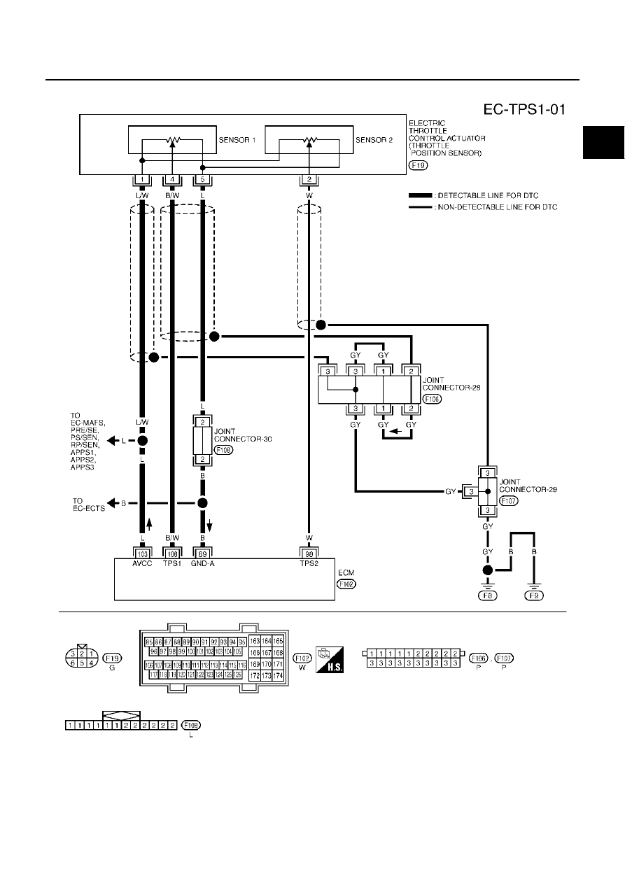
DTC P0222, P0223 TP SENSOR
EC-293
C
D
E
F
G
H
I
J
K
L
M
A
EC
Wiring Diagram
EBS00MDC
TBWM0125E