Infiniti F50. Manual - part 328


  Index      Infiniti     Infiniti F50 - service repair manual 2006 year


Search            


Content   ..  326  327  328  329   ..


Infiniti F50. Manual - part 328


VEHICLE INFORMATION AND INTEGRATED SWITCH SYSTEM /WITH NAVIGA-

TION SYSTEM

DI-155

C

D

E

F

G

H

I

J

L

M

A

B

DI

Multifunction Switch Self-Diagnosis Function

EKS006TV

It can check ON/OFF operation of each switch in the multifunction switch and diagnose the input signals to the
rear control switch (audio) and steering switch (audio).

STARTING THE SELF-DIAGNOSIS MODE

1.

Turn ignition switch from OFF to ACC.

2.

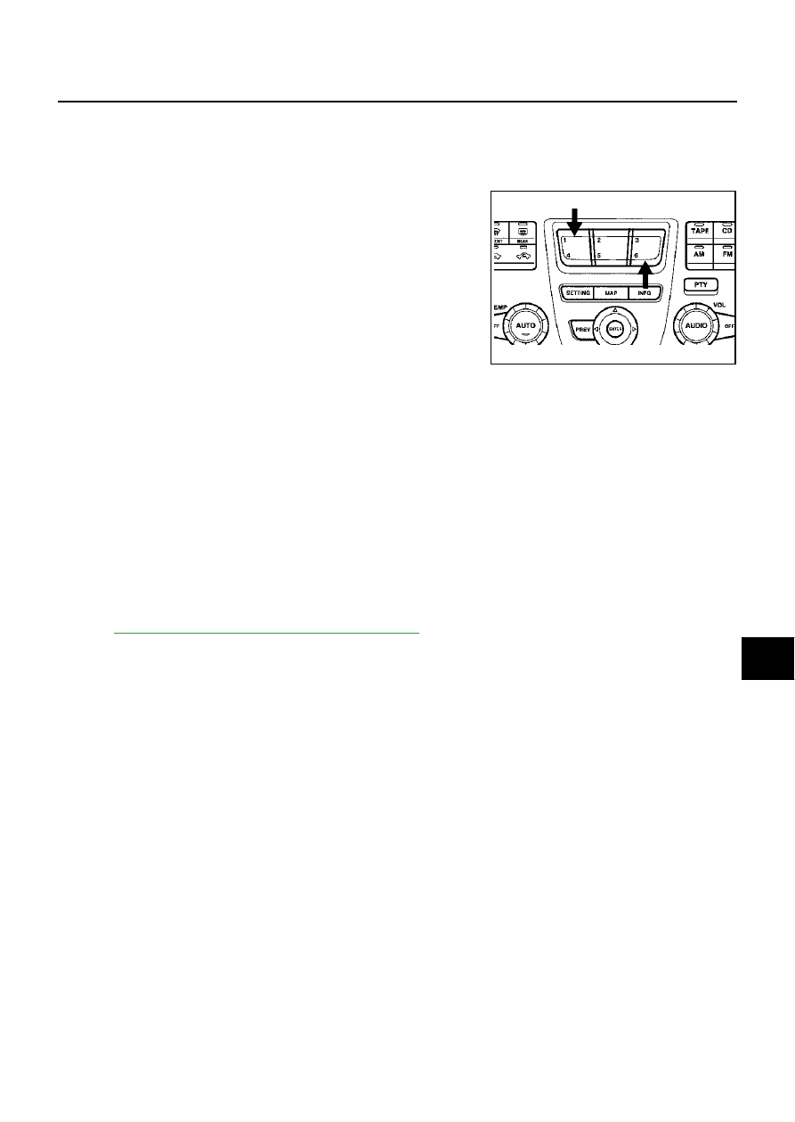
 Within 10 seconds press and hold the function switches “1” and
“6 ”simultaneously for 5 seconds.

Then the self-diagnosis operates.

EXITING THE SELF-DIAGNOSIS MODE

Turn ignition switch OFF, or press and hold the function switches “1” and “6” simultaneously for 5 seconds.
Then the self-diagnosis ends.

DIAGNOSIS FUNCTION 

It can illuminate all the indicators (LED) in the multifunction switch.

It can check for continuity of the switches by sounding the buzzer when the multifunction switch is
pressed.

It can check for continuity of harness between multifunction switch and rear control switch (audio), or
steering switch (audio).
NOTE:
When it check continuity of harness between multifunction switch and rear control switch (audio), rear
control cancel switch is OFF position.

Power Supply and Ground Circuit Check for AV and NAVI Control Unit

EKS006TY

Refer to 

AV-92, "Power Supply and Ground Circuit Check"

 .

SKIA0609E

DI-156

VEHICLE INFORMATION AND INTEGRATED SWITCH SYSTEM /WITH NAVIGA-

TION SYSTEM

Power Supply and Ground Circuit Inspection for Display

EKS006TZ

1. 

CHECK FUSES

Check 15A fuse [No. 52, located in fuse, fusible link and relay block (J/B)] is blown.
OK or NG

OK

>> GO TO 2.

NG

>> If fuse is blown, be sure to eliminate cause of malfunction before installing new fuse. Refer to 

PG-

2, "POWER SUPPLY ROUTING"

 .

2. 

CHECK POWER SUPPLY CIRCUIT

1.

Disconnect display connector. 

2.

Check voltage between display harness connector M82 termi-
nals 19 (L/OR), 21 (SB), 23 (SB) and ground.

OK or NG

OK

>> GO TO 3.

NG

>> Check harness for open or short between display and fuse.

3. 

CHECK GROUND CIRCUIT

Check continuity between display harness connector M82 terminal
22, 24 and ground.

OK or NG

OK

>> Inspection end.

NG

>> Repair harness or connector.

Terminals

Ignition switch position

(+)

(–)

OFF

ACC

ON

Connector

Terminal

(Wire color)

M82

19 (L/OR)

Ground

0V

Battery 
voltage

Battery 
voltage

21 (SB)

Ground

Battery 
voltage

Battery 
voltage

Battery 
voltage

23 (SB)

Ground

Battery 
voltage

Battery 
voltage

Battery 
voltage

SKIA0552E

Terminals

Continuity

(+)

(–)

Connector

Terminal

(Wire color)

M82

22 (B)

Ground

Yes

M82

24 (B)

Ground

Yes

SKIA0553E

VEHICLE INFORMATION AND INTEGRATED SWITCH SYSTEM /WITH NAVIGA-

TION SYSTEM

DI-157

C

D

E

F

G

H

I

J

L

M

A

B

DI

Power Supply and Ground Circuit Inspection for Multifunction Switch

EKS006U0

1. 

CHECK POWER SUPPLY CIRCUIT

1.

Disconnect multifunction switch connector.

2.

Check voltage between multifunction switch harness connector
M83 terminal 1 (L/OR) and ground.

OK or NG

OK

>> GO TO 3.

NG

>> Check harness for open or short between multifunction switch and fuse.

2. 

CHECK GROUND CIRCUIT

Check continuity between multifunction switch harness connector
M83 terminal 2 (B) and ground.

OK or NG

OK

>> Multifunction switch is OK.

NG

>> Repair harness or connector.

Terminals

Ignition switch position

(+)

(–)

OFF

ACC

ON

Connector

Terminal

(Wire color)

M83

1 (L/OR)

Ground

0V

Battery 
voltage

Battery 
voltage

SKIA0534E

Continuity should exist.

SKIA0535E

DI-158

VEHICLE INFORMATION AND INTEGRATED SWITCH SYSTEM /WITH NAVIGA-

TION SYSTEM

No Fuel Information Is Displayed/No Warning Message Is Displayed

EKS006U1

1. 

CHECK HARNESS

1.

Turn the ignition switch OFF.

2.

Disconnect connectors of combination meter, BCM, and AV and NAVI control unit.

3.

Check continuity between AV and NAVI control unit and combination meter.

4.

Check continuity between AV and NAVI control unit and ground.

OK or NG

OK

>> GO TO 2.

NG

>> Repair harness.

2. 

CHECK COMMUNICATION SIGNAL (AV–ME)

1.

Connect connectors of combination meter, BCM, and AV and NAVI control unit.

2.

Turn the ignition switch ON.

3.

Check the signal between AV and NAVI control unit harness
connector B29 terminal 33 (LG) and ground with CONSULT-ll or
oscilloscope.

OK or NG

OK

>> GO TO 3.

NG

>> Replace AV and NAVI control unit

3. 

CHECK COMMUNICATION SIGNAL (ME–AV)

1.

Turn ignition switch to ON and display “VEHICLE ELECTRONIC SYSTEMS”screen.

2.

Check the signal between AV and NAVI control unit harness
connector B29 terminal 32(PU) and ground with CONSULT-ll or
oscilloscope.

OK or NG

OK

>> Replace AV and NAVI control unit.

NG

>> Replace combination meter,.

Terminals

Continuity

AV and NAVI control unit (+)

Combination meter (–)

Connector

Terminal 

(Wire color)

Connector

Terminal 

(Wire color)

B29

33 (LG)

M41

7 (LG)

YES

B29

32 (PU)

M41

6 (PU)

YES

Terminals

Continuity

AV and NAVI control unit (+)

(–)

Connector

Terminal 

(Wire color)

B29

33 (LG)

Ground

NO

32 (PU)

SKIA3533E

33 (LG) – Ground

: Refer to 

AV-73, "Terminals and 

Reference Value for AV and NAVI 
Control unit"

 .

SKIA3534E

32 (PU) – Ground

: Refer to 

AV-73, "Terminals and 

Reference Value for AV and NAVI 
Control unit"

 .

SKIA3535E


Content   ..  326  327  328  329   ..