Infiniti F50. Manual - part 305
WARNING CHIME
DI-63
C
D
E
F
G
H
I
J
L
M
A
B
DI
Terminals and Reference Value Chart for BCM
EKS0010Z
Work Flow
EKS001QX
1.
Check the symptom and customer's requests.
2.
Understand the outline of system. Refer to
3.
Perform the preliminary check. Refer to
DI-64, "Preliminary Inspection"
4.
Referring to trouble diagnosis chart, repair or replace the cause of the malfunction. Refer to
5.
Does warning chime system operate normally? If it operates normally, GO TO step 6. If not, GO TO step
4.
6.
Inspection END.
Terminal
No.
Wire
color
Item
Condition
Reference value
3
R/L
Tail lamp relay
Lighting switch,
Position: 1ST, 2ND
ON
Battery voltage
OFF
Approx. 0V
12
BR
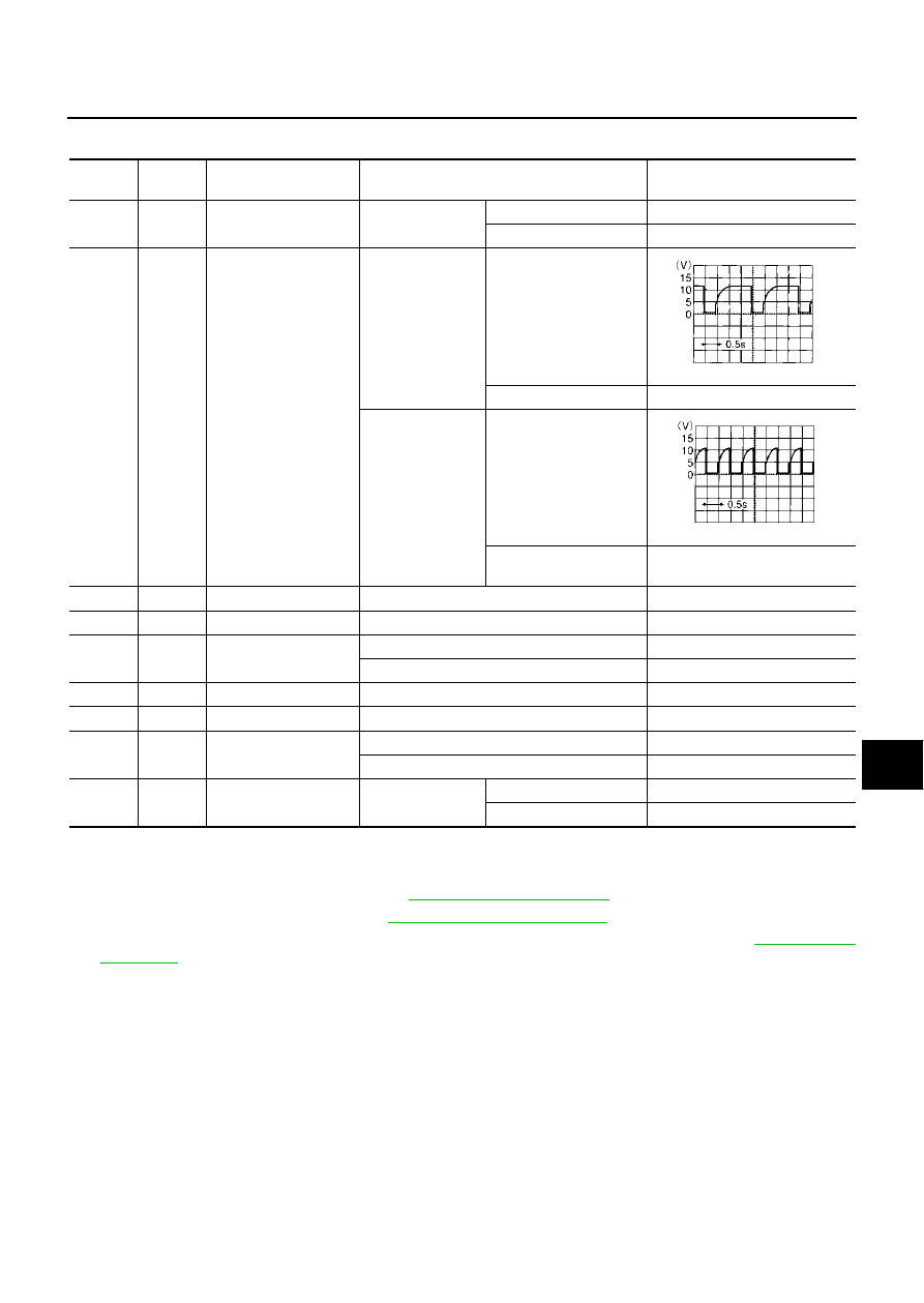
Warning chime input
signal
(Ignition key warn-
ing chime)
Front door (driver
side): OPEN
Lighting switch:
OFF
Key is inserted.
Key is removed.
Battery voltage
(Light warning
chime)
Lighting switch,
Position 1ST, 2ND
Front door (driver side):
Open
Front door (driver side):
Closed
Battery voltage
56
B
Ground
—
Approx. 0V
68
W/B
Ignition switch (ON)
Ignition switch is in “ON” position.
Battery voltage
69
PU/W
Key switch and key lock
solenoid (key switch)
Key is removed (key switch: OFF).
Approx. 0V
Key is inserted (key switch: ON).
Battery voltage
105
Y/L
Power source (BAT)
—
Battery voltage
113
B
Ground
—
Approx. 0V
142
W/R
Front door switch (driver
side)
ON (Open)
Approx. 0V
OFF (Closed)
Battery voltage
147
G/W
Seat belt buckle switch
(driver side)
Ignition switch is
“ON” position.
Fasten
Approx. 5V
Unfasten
Approx. 0V
ELN0529D
ELN0530D